J. Kissel, S. Koehlenbeck [remote], J. Wright, M. Simmonds
Here, we post an aLOG to cover the whole week's slog, picking up where we we left off at that end of last week (LHO:90332).
%%%%%%%%%%%%%
Executive Summary: the remaining outstanding issue to solve before instal for the SPI pathfinder is the irregular and intermittent drift in heterodyne efficiency in the SPI's MEAS IFO (item (3) from the list of issues after finishing re-assembly up to D2400107-v5 after ECR E2600106). Importantly, we've seen this issue in the MEAS IFO even with the previous version of the assembly back in Mar 2026.
After a week of hard work, we've ruled out just about everything that it could be *except* for flaws in the alignment system of the picomotor-actuated IXM100 mirror mounts which steer the MEAS beam to the MEAS IFO (see D2400107 for the annotated layout).
%%%%%%%%%%%%%
I spend the rest of the aLOG summarizing what we've ruled out and how. Remember -- thru out all of these studies, the REF IFO remains a rock-solid high efficiency, and the power monitor PDs so the input power on the MEAS and REF is quite stable.
And a reminder for those not-so-versed in heterodyne interferometers, the primary metric is the efficiency, defined as
eta = [peak-to-peak beat note amplitude] / (2 * beat note mean)
(nominally 100% if the mode overlap between two interfered beams is perfect).
"Drift" of this efficiency means that -- without
Electronics Issues with the IFO MEAS PDs.
- Suspected cause: "maybe the bias voltage is drifting?" "Something's going on with the electronic ground because we're only looking at the positive leg?"
- RULED OUT: we swapped the REF B PD (which had been measuring a rock-solid, high efficiency from the REF IFO) into the MEAS B PD position, and had it measure the MEAS IFO beam. The drift was measured by the REF B PD as well. This convinces us that "it's on the incoming interfered beam.
- PLUS: The bias voltage is supplied by a single circuit for all PDs in the ISIK transceiver system, so the bias-related issues would be common to REF or MEAS PDs.
Spurious drive on the the picomotors
- Suspected cause: "maybe the ambient electric field in the room is driving the floating pins of the picomotors, pushing the mirrors around?"
- RULED OUT: At the start of the week, the picomotor signal chain was hooked up as designed from motor might-mouse to quadrupus to mock feedthru and out a ~6 ft D25 in-air cable that had been used for testing.
(a) Just like we'd already done with the PDs, we hooked up ever single picomotor pin to rack power supply ground via a breakout board and clip leads at the end of the in-air cable. Still see drifts.
(b) We also tried simply disconnecting all picomotors at their might-mouse connector. Still see drifts.
Clipping along the MEAS path into the MEAS IFO
- Suspected cause: "If there's some sort of clipping anywhere, you lose efficiency. If it's just barely clipping, the clipper might be moving / breathing with the environment."
- RULED OUT:
(a)Checked centering on M_M1, M_B4, M_M2, M_B3, and the two MEAS IFO PDs, and can confirm they're either
:: On Optics -- offset in yaw by design (but still several beam diameters away from the optic barrel in REFL or TRANS), or
:: Well-centered.
(b) We'd started the week with the M_M4 and M_M5 mirror mounts and adapters in place (with no dump in either). The beam comfortably goes through the transmission ports of both adapters. But, over the course of the week, as we ruled out "everything else" out, we removed them so now they're off the board. We still see drift.
(c) Confirmed that "tight-squeezes" between beam dumps still allow for at least ~1x beam diameter of clearance (on an IR card).
Optics' Quality, dust and schmutz
- Suspected cause: "If there's a scratch or schmutz on the optic, then maybe as the beam alignment drifts, the optical quality of the reflected beam is intermittently spoiled."
- RULED OUT: We replaced all optics in the MEAS path with just-as-good, same production/coating run, equally class-A cleaned, high quality mirrors. Still see drifts.
Beam quality and Optical Mode-shape
- Suspected cause: "We haven't found anything, so let's look at the beam shape on a profiler. This should be the definitive answer."
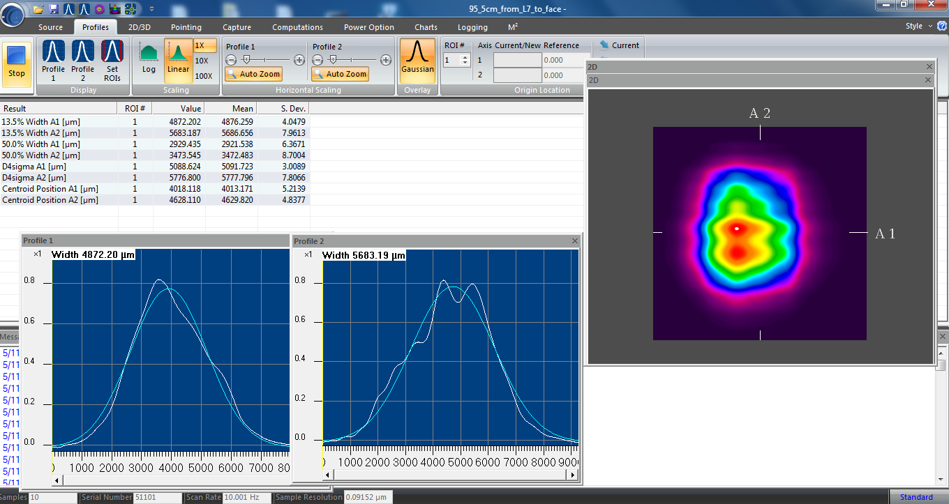
- RULED OUT: We removed IFO_MEAS_B, and projected the beam on to a WinCam beam profiler head, and read it's data out in the WinCam software. We looked at the beam both with a very slow heterodyne beat-note of 250 mHz, and the nominal 4096 Hz (adjusting the modulation frequency at our commercial RF source's digital interface).
(a) With the MEAS IFO's alignment just tuned up, Compared mode shape and alignment during episodes of high and low efficiency, and we see nothing but excellent beam shape. (In the slow-beat-note-configuration) the only difference in profile results is the expected lower intensity when the efficiency was low.
(b) We deliberately misaligned the REF and MEAS beams going into the MEAS IFO such that both beams still visible on the WinCam profile, but not interfering. No movement of beams, no mode shape change, no beam diameter change, nothing that would cause the efficiency drift.
Polarization
- Suspected cause: "The last thing that it could be if it's not mode shape / quality / alignment is polarization drift..."
- RULED OUT: With the same IFO_MEAS_B beam, we inserted a polarizing beam splitter and monitored the s-pol power in the reflected port. S-pol (max) power (at peaks of beat note) is stable at ~10-15 [microWatt] during periods high and low efficiency. The designed p-pol light at IFO is at the 5-10 [milliWatt] level, so the extinction ratio is awesome. And we still see drifts. This also rules out, e.g. the nightmare scenario that the optics' mount PEEK set screw -- only on the MEAS path optics -- are cranked on the optic so hard that is causes birefringence.
- PLUS: if there was a board-level polarization drift, the REF IFO would also be seeing this same drift.
Optical Power fluctuations (Sanity Check)
- Suspected cause: "I know you don't see any drift in the REF IFO, but ... is the input power drifting?"
- RULED OUT:
(a) The REF IFO beam samples the same beams as the MEAS IFO, and
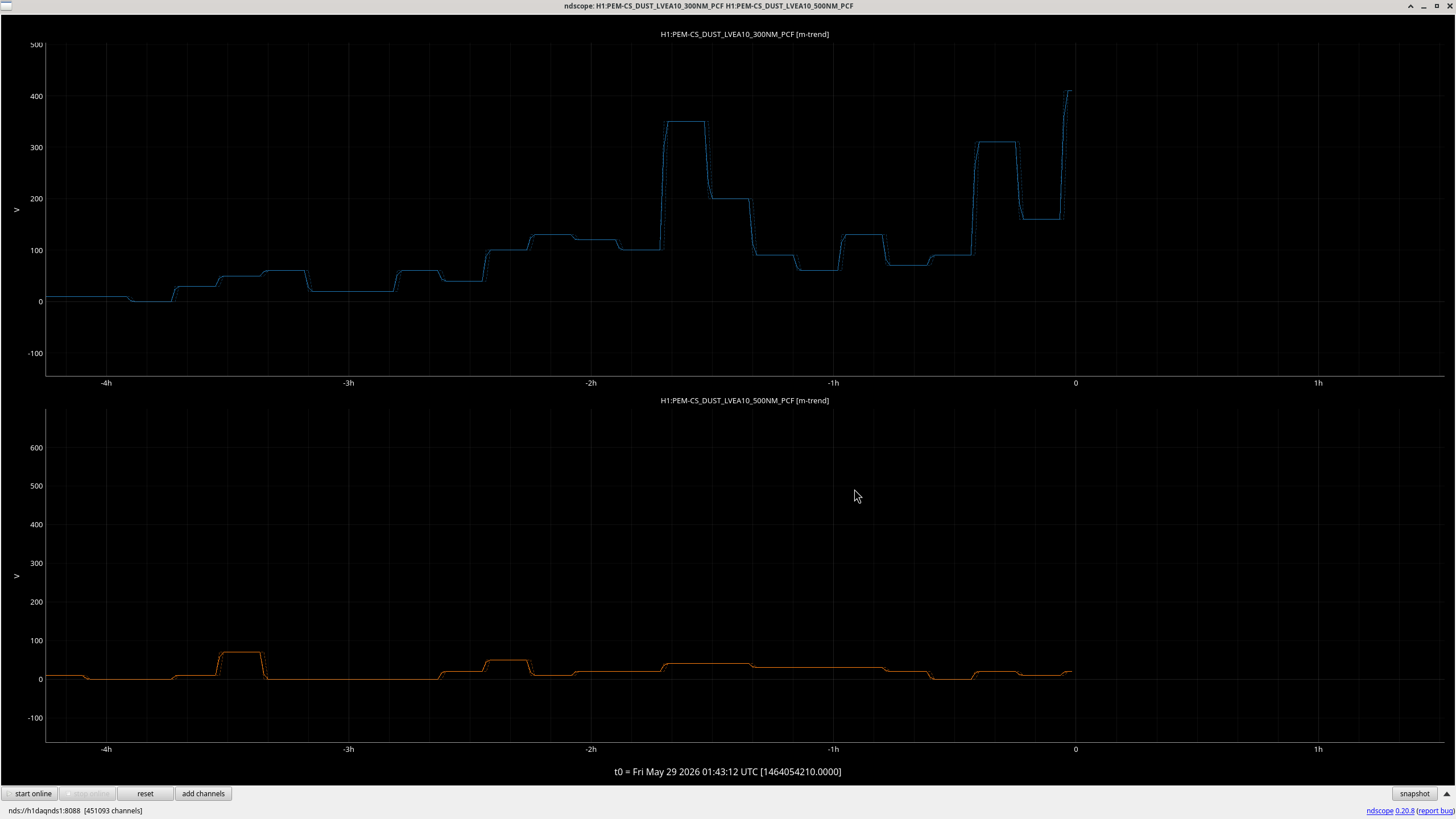
(b) Yes, we've had the power monitor PDs up on the o-cope for days, and we see no obvious or reproducible correlation.
RF Modulation Modulation power fluctuations (Sanity Check)
- Suspected cause: "I know you don't see any drift in the REF IFO, but ... did you check the RF electronics?"
- RULED OUT: Yup, we've had the RF power monitor outputs of the laser prep chassis on the scope most of the time, and these are rock-solid and at the expected level.
Environment (Insanity Check)
- Suspected Cause: "The only thing that intermittently drifts on the minutes time-scales you're seeing is things like air currents and thermal effects."
- RULED OUT: We tried SO MANY different combinations of
(a) Clean room Lights ON/OFF
(b) Room Lights ON/OFF
(c) Clean room Fans ON/OFF
(d) People in/out of clean room
(e) People in different positions in the clean room
and none of these showed obvious or reproducible correlation.
Conclusion -- It's gotta be the mechanical assembly of the picomotors in the IXM100 mounts.
The picomotor-actuated assembly process was documented in LHO:87497 following the assembly procedure E2500163.
[1] The most accurate mechanical drawing we have the IXM mount itself D1100362
[2] The vendor drawings of the picomotor E1000197
[3] The most accurate assembly of a pico-actuated IXM mounts D1500494 and D2100433
[4] The SPI's drawings for its IXM mounts D2400144 and D2400145
Looking at the assemblies:
- We're worried that the pico-motor "stopper nut" is pushing the movable-mounting plate (item 1 in [1]), rather than the pico-motor's ball bearing. And somehow this poor kinematic connection is drifting and slipping with the environment or something.
- The v-groove of the item 7 in [1] carbide plate faces toward the pitch actuator, and away from the yaw actuator. While this is the right thing to do to prevent over constraint -- because the same part is used in both actuator interfaces, the ball of the pitch actuator (be it manual- or pico- driven) will sit "deeper" in longitudinal than the yaw actuator. The yaw actuators' stopper nuts all easily clear the movable mounting plate, but the pitch actuators do not.
- The manually driven IXM100s show there's no issue, given that the cupped 8-100 alignment screw clears the carbide plate holes in the moveable optic-mounting plate.
ACTIONS FOR NEXT WEEK
We're at our wits end, and considering just ax'ing the picomotor actuation on M_B4 and M_M2. In fact, we've already replaced the mount of M_M2 with a manually driven IXM100, and may do so for M_B4 if we find enough clean IXM100 mounts.
However, we've got some ideas to fix the problem and still have remote actuation:
- Place a washer between the carbide plate and the front plate.
- Remove the stopper nut.
- Mill away parts of the front plate.
- Get a thicker carbide plate.
- Use only one pico-motor per holder.
Pictures and further commentary to come in due time.


We spoke with Patrick and he says all the Beckhoff items in the list can wait till Monday. Ditto HWS.
Erik is working on the h1cdsrfm end-station Adnaco and Timing Master issues. He is on his way to the end stations and H2 building.