david.barker@LIGO.ORG - posted 11:52, Thursday 11 February 2016 (25504)
faster sus computers occasionally glitching SEI and ISC end station models
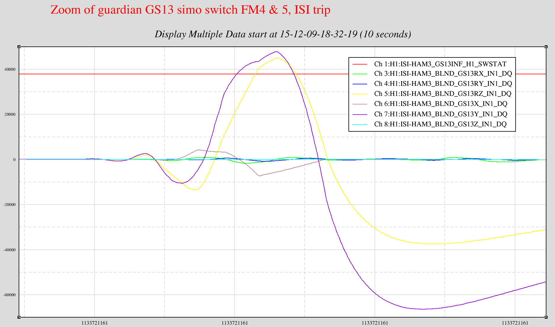
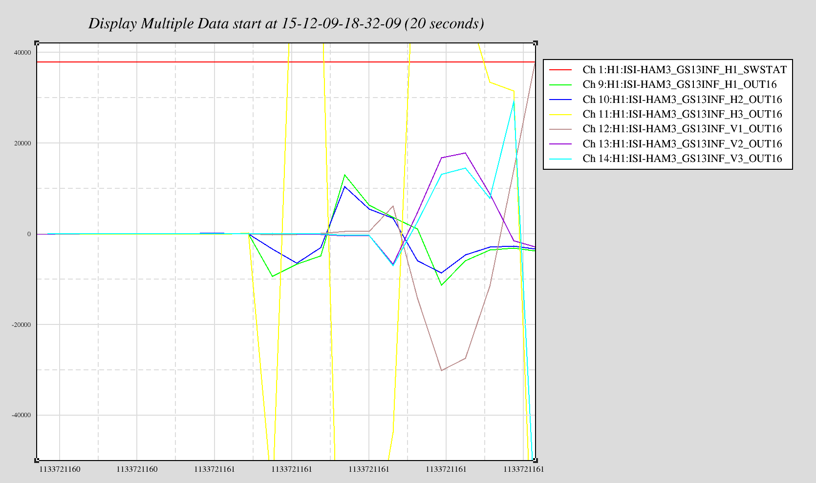
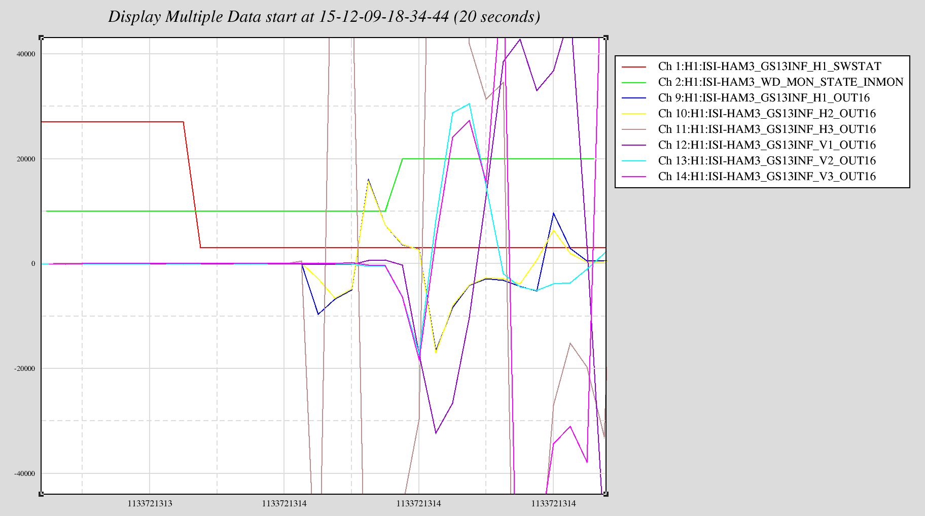
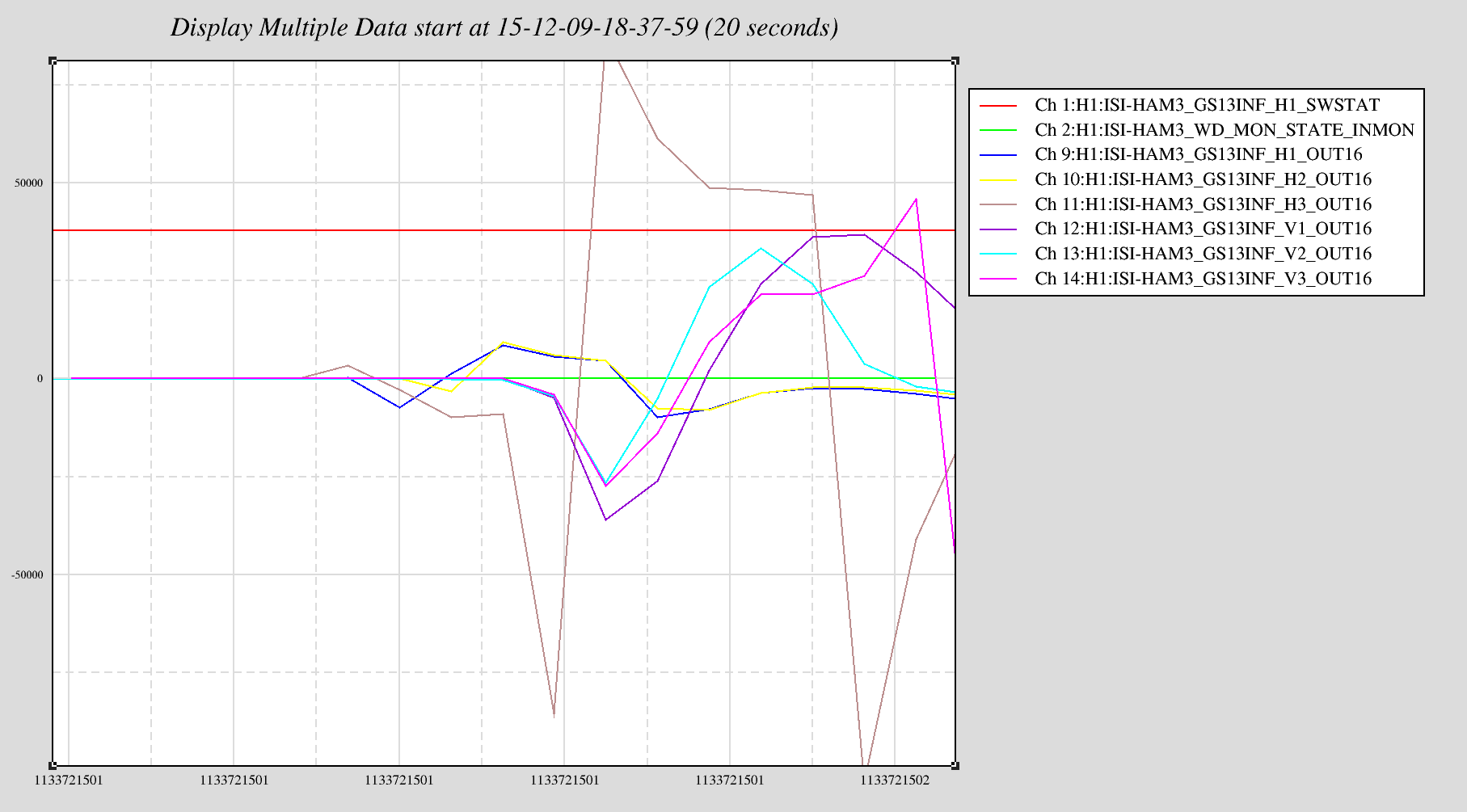
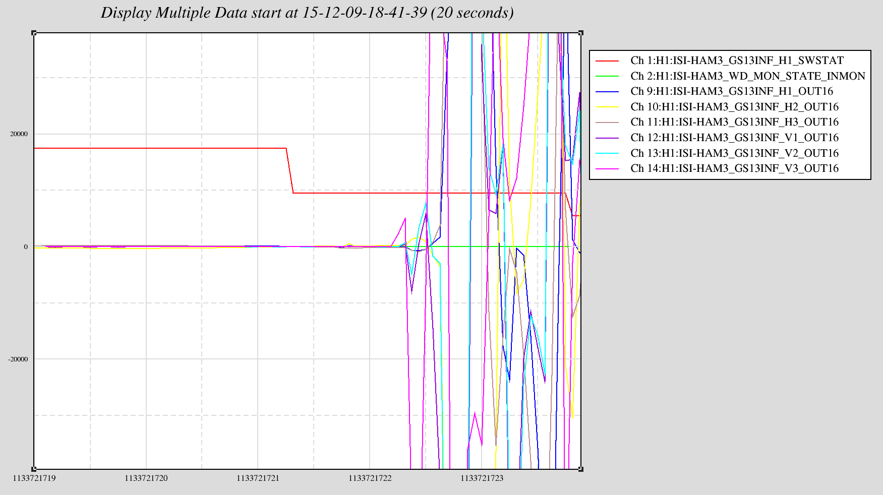
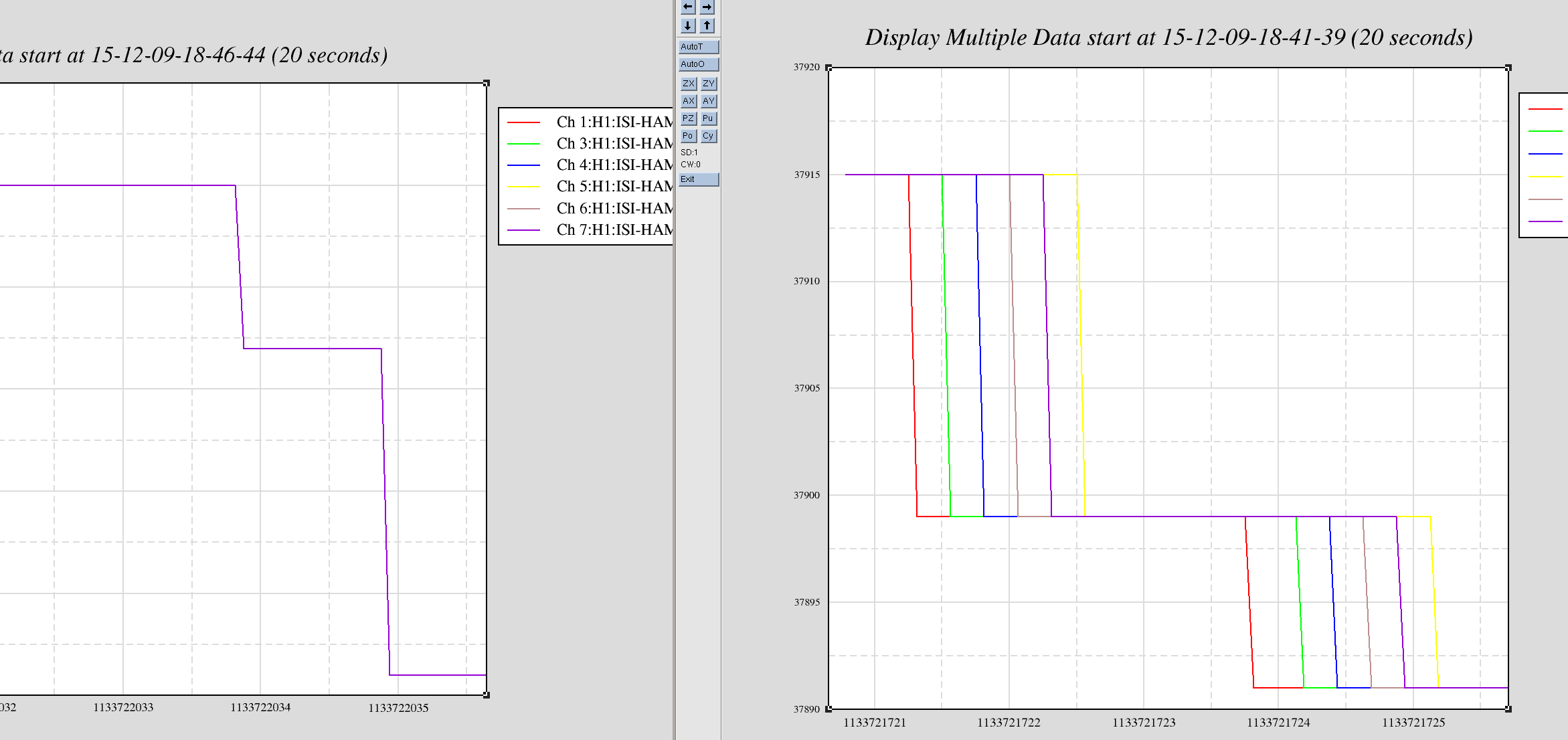
Most cpu overruns associated with the faster SUS computers (which were installed in the end stations this Tuesday) only glitch the SUS-IOP and SUS-ETMX,Y models. Once in a while the glitch extends to the SEI IOP/ISI model and the ISC/ALS models and also glitches the SUS-TMS and SUS-PI models.
To keep the overview GREEN and help with trending, I have extended my end_station_sus_diag_resets.bsh script to clear these additional models. This script is ran roughly once a minute on opsws16.