rich.abbott@LIGO.ORG - posted 15:17, Thursday 29 January 2015 (16355)
Installed Fast Shutter Driver
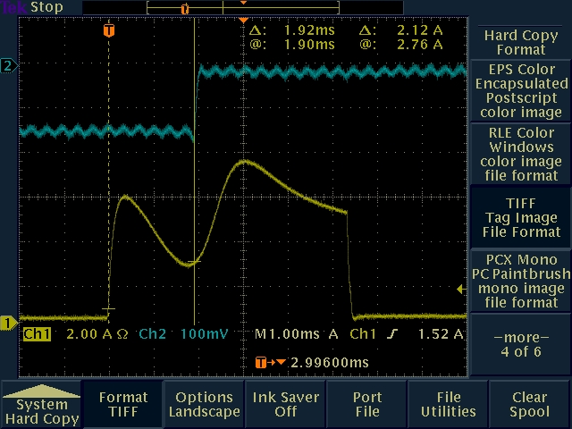
Filiberto, Richard, Rich

Installed Fast Shutter Driver Chassis S1400582 into ISC Rack 5 at U-height 6.  The system performs well in terms of reliably blocking light upon receipt of a trigger input (1.92milliseconds to block).  The remote control signals are functional in terms of the hardware, but there is still a reboot of the Beckhoff system needed to load the necessary code.  We will do this tomorrow to avoid messing with commissioning.

The solution is as follows:
1.  250 VDC on Kepco Supply, this corresponds to 243 VDC on the internal energy storage capacitors and is visible on the front panel LCD display on the shutter driver.
2.  5.4 millisecond applied pulse width
3.  20 ohms series resistor

Here is the rule for using the shutter to prevent damage to photodiodes in HAM6:
We must not lock the interferometer at high power(>10 watts) without the HV READY indicating the shutter is charged, AND no FAULT condition.  Both these parameters are reported via the Beckhoff interface from the shutter driver.

Some not so obvious factoids about the shutter system:
1.  The shutter is triggered to fire by a trigger signal that falls from 5 to 0 volts indicating the light level on the trigger diode has exceeded the maximum allowable setpoint.  Right now, the shutter controller latches this low voltage state.  The shutter driver deliberately interprets a continuous low voltage input as evidence that the shutter controller is either unpowered, broken, or disconnected, and will report a fault condition after 5 seconds.
2.  The shutter driver needs about 10 seconds to recharge after firing during which time you can not trigger it to drive the shutter.  This is deliberate as firing the shutter with an arbitrary low voltage can cause the shutter to be damaged.
3.  If the output drive cable delivering the pulse to the shutter is disconnected anywhere in the chain, the shutter will go into a FAULT state and won't do anything until the FAULT state is fixed.  The shutter driver also generates a FAULT if any internal low voltage used in the shutter driver is out of spec by more than 10% from nominal.

The attached image shows a timing measurement made by measuring the applied current to the shutter coil (shown in yellow obtained by using a clamp-on current probe) and the DC light level (taken on a breakout board on AS WFS A DC Channel 1).  The time between the rising edge of the current pulse and the falling DC voltage level is about 1.92mSec
Images attached to this report