peter.king@LIGO.ORG - posted 04:39, Tuesday 04 October 2016 (30198)
flow sensor signals
Attached are what the signals from the Kobold vortex flow sensors look like as read across
a 240-ohm resistor.
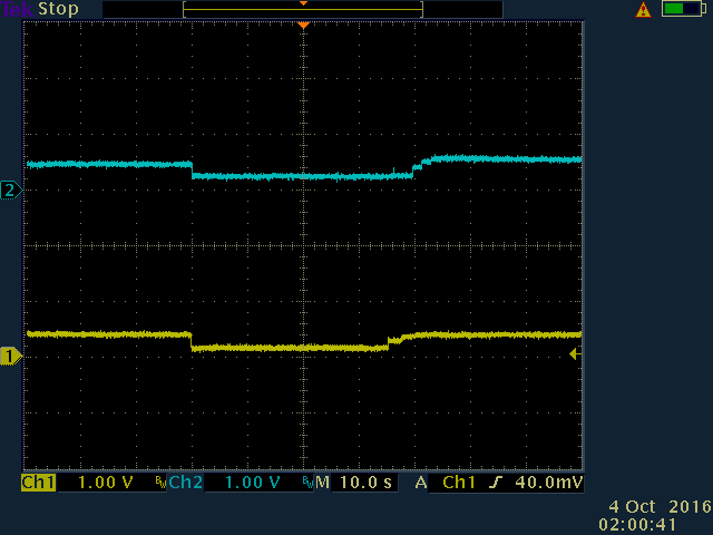
TEK00001.png shows the signals corresponding to switching off and back on the chiller.
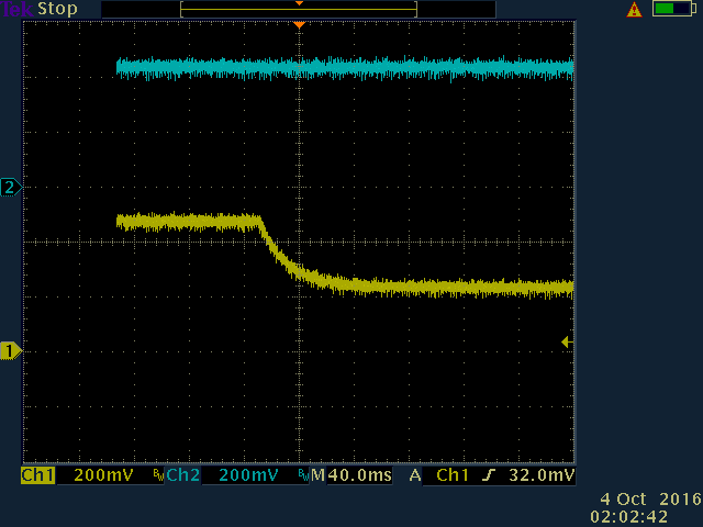
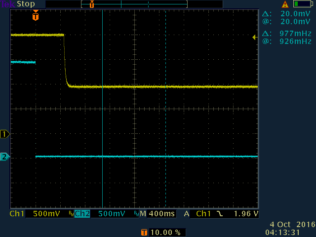
TEK00002.png shows the signal decay from the power meter circuit flow sensor when the
chiller is switched off.
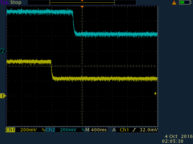
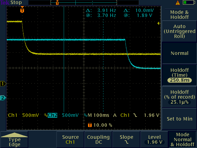
TEK00004.png both signals when the chiller is switched off.
TEK00005.png looking for glitches when one of the sensors drops
TEK00007.png both signals when the chiller is switched off, only this this both outputs
fell to zero within the same oscilloscope sweep
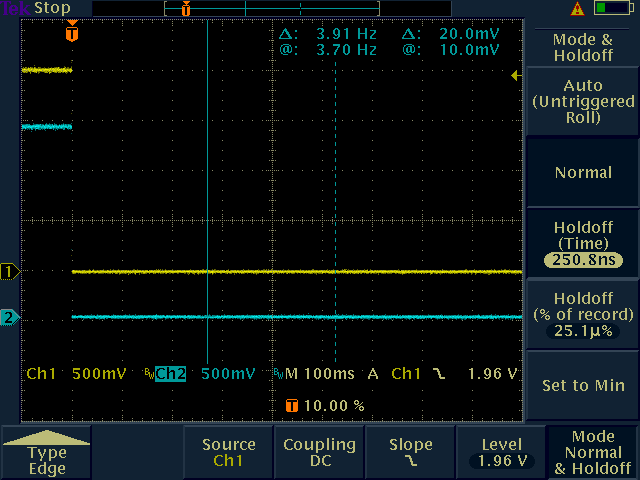
TEK00008.png both flow sensors were physically disconnected to simulate a power failure or
dramatic sensor failure.
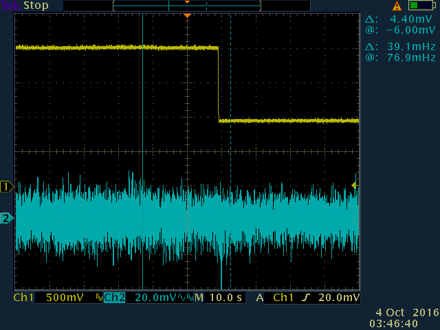
TEK00010.png the power meter flow sensor output was switched off
There are a couple of things of interest to note:
1. The signal from the sensors is much "cleaner" than what comes out of data acquisition,
most likely due to the digitisation of the readout Beckhoff terminal.
2. Using an AC mains powered oscilloscope introduces a large 60 Hz signal on top of whatever
is there. A battery power oscilloscope was used for these measurements.
Images attached to this report