Daniel, Kiwamu per WP6650,
We made two major changes to IOO today as follows.
- The IMC locking RFPD (36322) was replaced by the one with the correct resonant frequency.
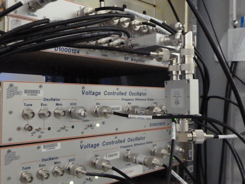
- A new modulation path for 118 MHz was added to the existing 24 MHz modulation path via a power combiner.
After these tasks, we have confirmed that the IMC could still lock with an UGF of 50 kHz (which had been 54-ish kHz before we made changes today, approximately corresponding to a 1 dB loss in the sensing system). Tomorrow, we will try to measure the modulation index for 118 MHz using the Michelson fringes.
[IMC length RFPD]
The old unit (S1203263) was replaced by the one with the correct resonant circuit (S1203775). I have repeated the same measurement as yesterday with the AM laser (36322) to check out the response of the new RFPD. The first attached figure shows comparison of the new and old RFPD responses. The magnitude at 24 MHz was found to be lower than that with the old one by half a dB. So the response is virtually unchanged at 24 MHz. The raw data is attached as well.

I made sure about the alignment of the beam onto the RFPD by touching the 2" steering mirror in front of it. I also made sure that the reflection from the RFPD was dumped properly with a razor blade.
[Addition of 118 MHz modulation]
We newly installed two IFR function generators in an ISC rack in the CER. One of them provide us with the modulation rf source at 118 MHz while the other does for the demodulation at 72 MHz or whatever frequency we desire. The 118 MHz generator was then hooked up to an RF amplifier, ZHL-1-2W, and then to the patch panel which transfers it to the ISC field racks by the PSL. Then, the 118 MHz signals is combined with the existing 24 MHz modulation signal via a power combiner, MECA 2-way combiner. As it turned out that the power combiner gave us a relatively high insertion loss of ~3 dB, we decided to increase the rf power for 24 MHz as a compensation. We increased it by installing another MECA 2-way combiner and let it do the coherent sum. So in total we have installed two 2-way combiner in series as seen in the attached picture.
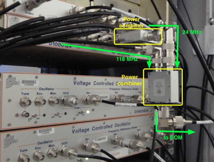
We also studied rf losses for 118 MHz and found extra frequency dependent losses in the cable that connects the field and remote racks. The cable loss for 118 MHz was found to be higher than that for 24 MHz by a couple of dB. In the end, we measured an rf power of 30 dBm for 118 MHz at the output of the last power combiner, which we think is reasonably high and not too high for causing serious problems with the EOM. Note that we tried inserting a balun which turned out to be as lossy as 3-4 dB. So we decided not to use a balun for 118 MHz. We are thinking of installing a DC block instead.
As this setup messed up the rf phase, we then re-adjusted the delay of the delay line unit for 24 MHz, by flipping 1 and 2 nsec switches. This gave us almost the same UGF of 50 kHz when the IMC was locked with a 2 W input and with the new RFPD in use. Good.

The 118 MHz phase modulation capability is for a new scheme of alignment sensing for the SRM, described in T1700215.
Hooked up the demodulation chain by switching all 90 MHz sensors at the AS port to 72 MHz. This includes the two ASC AS WFS and the LSC ASAIR_B.
The modulation frequencies are:
- fmain = 9.100230 MHz
- fmod = 13 * fmain = 118.302990 MHz
- fdemod = 8 * fmain = 72.801840 MHz
Currently, the demodulation chain is set with a 100 Hz offset to 72.801940 MHz. This means the DC signal will appear at 100 Hz which should allow us to measure the modulation index.
The 30 dBm RF power to the modulator was measured with the signal source set to 13 dBm. It is currently set to -10 dBm, but can easily be increased when needed.
The 8th and 13th harmonics are driven by two aeroflex 2023A which are synchronized to the external 10 MHz source. We also reinstalled the 2023A RF source used for diagnostics. I would expect the RF phase between the 2023A to be stable, but not relative to the OCXO.
Something is odd here.  The serial numbers may be backwards.  Here's why I think that:

The "old" RFPD is listed in this log entry as SN S1203263
The "new" RFPD is listed in this log entry as SN S1203775

Unless someone has re-tuned things from the original values, my records indicate S1203775 is actually tuned for 21.5MHz, which would make it a PSL FSS spare.  The other unit (S1203263) is tuned for 24.078MHz and was intended to lock the IMC.

It would appear as though the log entry may have swapped the serial numbers.
Rich,
You are right, I had them mixed up in the above entry. It should read, "S1203775 was replaced by S1203263". Additionally, the label in the plot is wrong in the same manner. Sorry for confusion.