This is from last week.
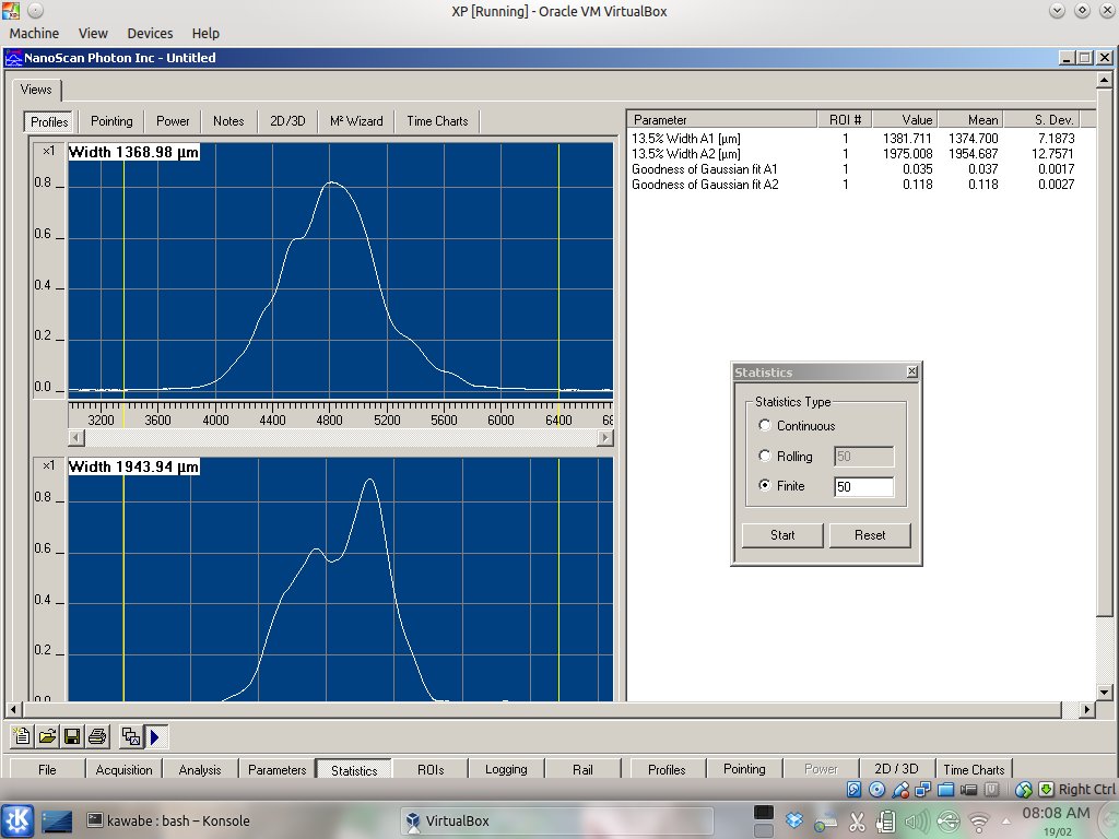
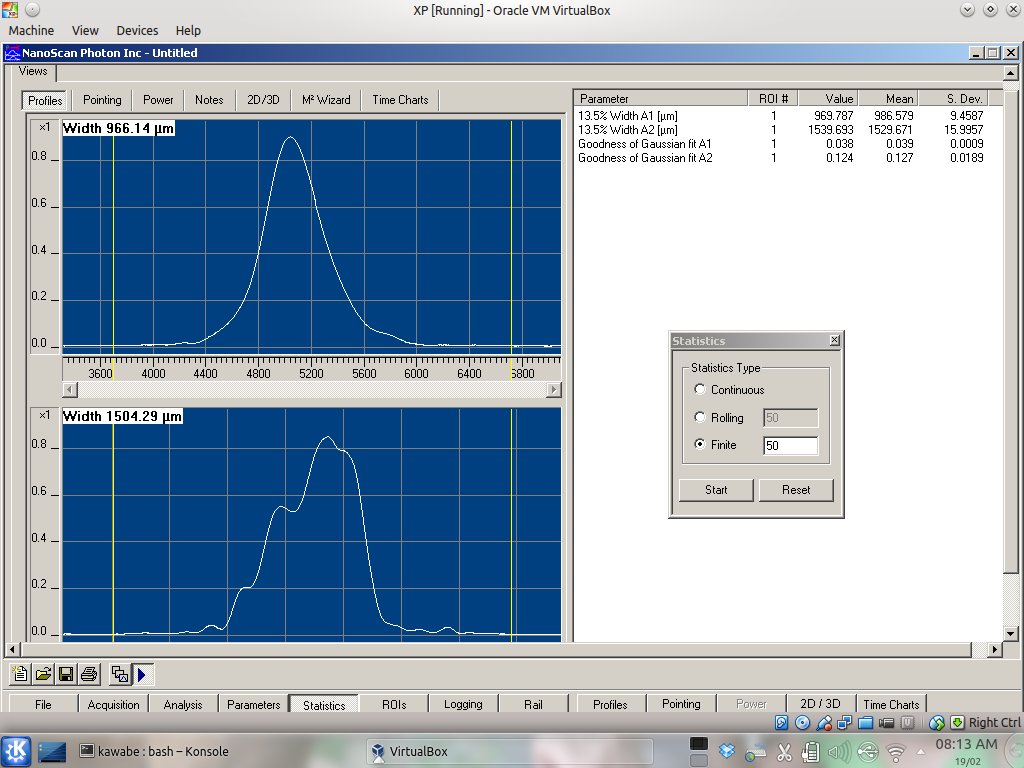
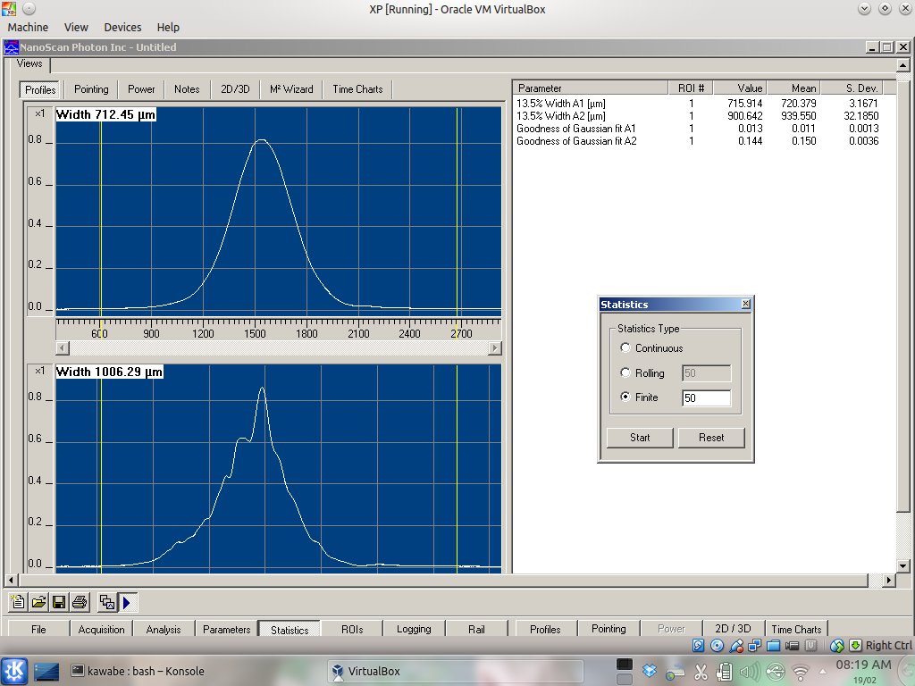
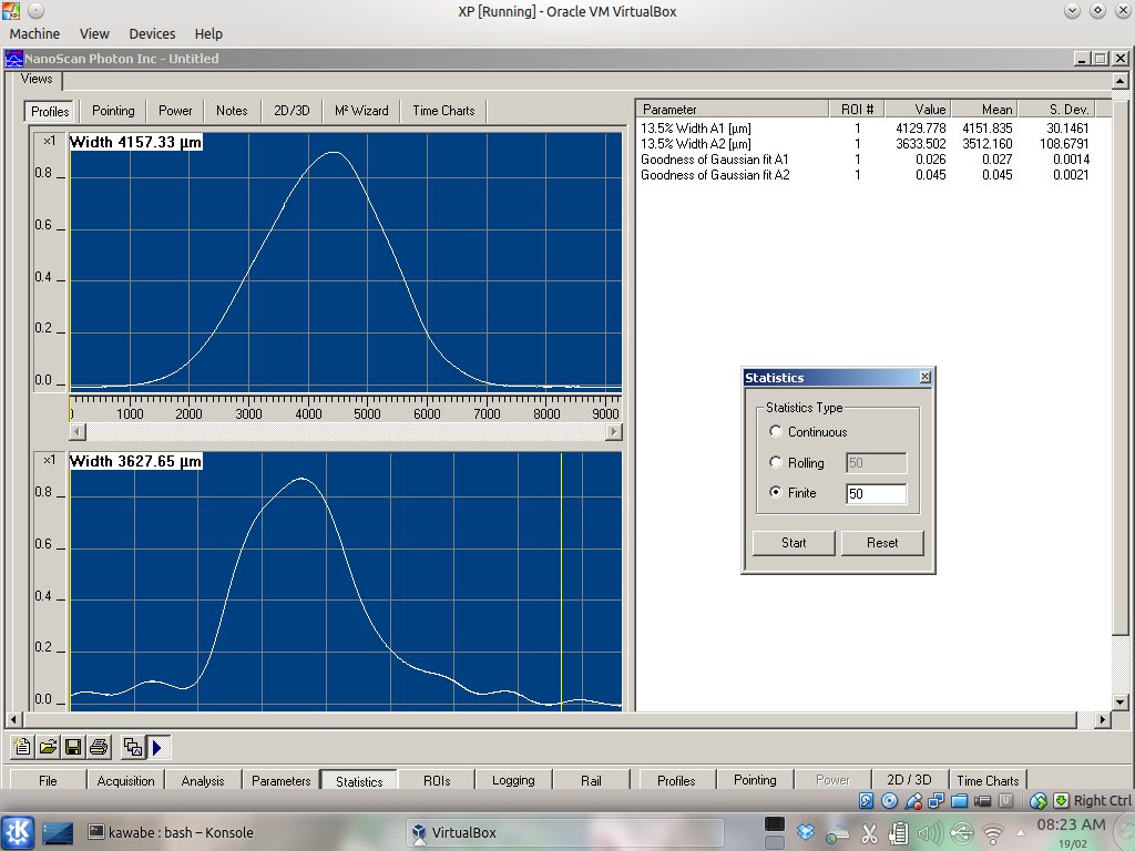
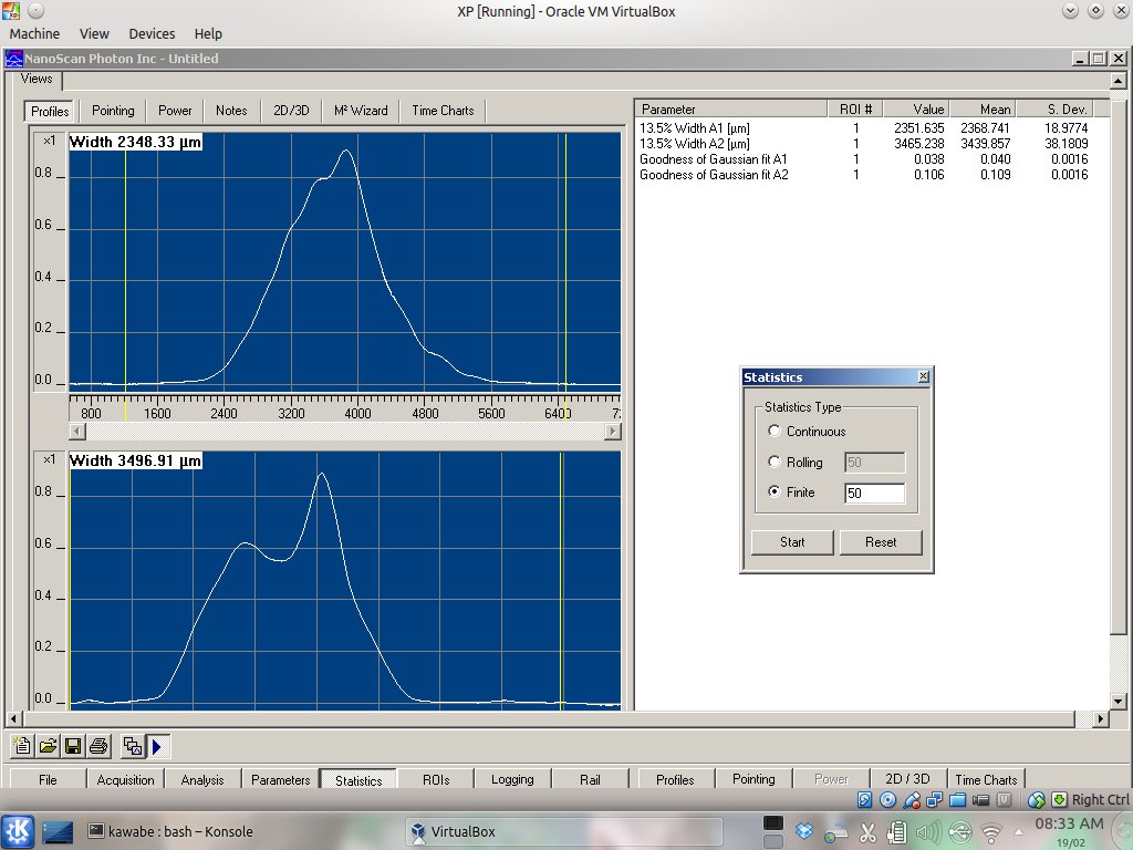
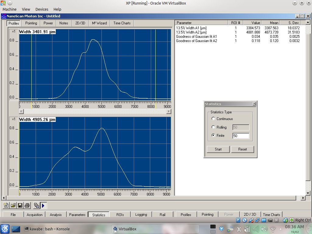
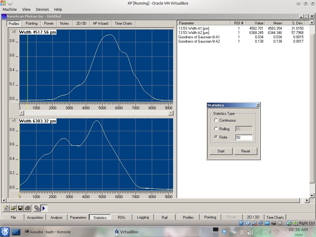
We briefly measured the distance between optics and such, and used nanoscan to measure beam width/profile at various places though they were very very ugly.
See attached scribbling for layout (all dimensions in inches). Mirror names are arbitrary.
Measurement points are indicated by alphabet from A to I. Measurement points with prime (G'-I') means that the first lens in WFSB path (LWFSB1) was removed during the measurement.
The rest of the attachements are the nanoscan result. WFSB1.jpg-WFSB4.jpg=measurement point A-D. WFSA1.jpg and WFSA2.jpg=measurement point E and F. WFSC1.jpg-WFSC3.jpg=measurement point G', H' and I'.
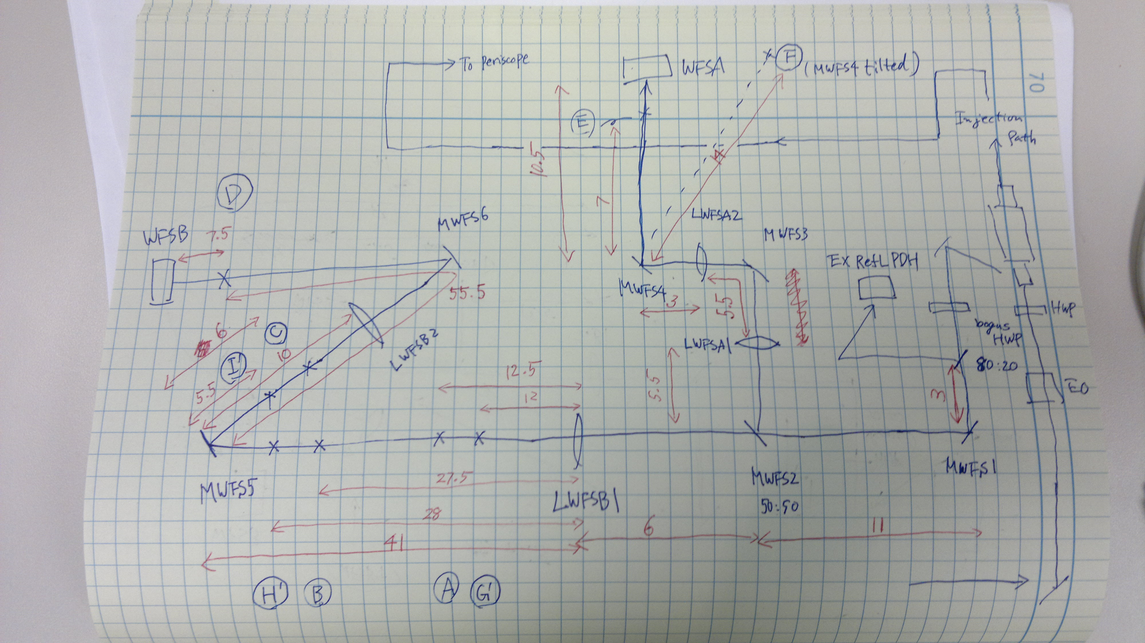


The lenses as installed are:
LWFSA1 +250mm
LWFSA2 -75mm
LWFSB1 +250mm
LWFSB2 -100mm
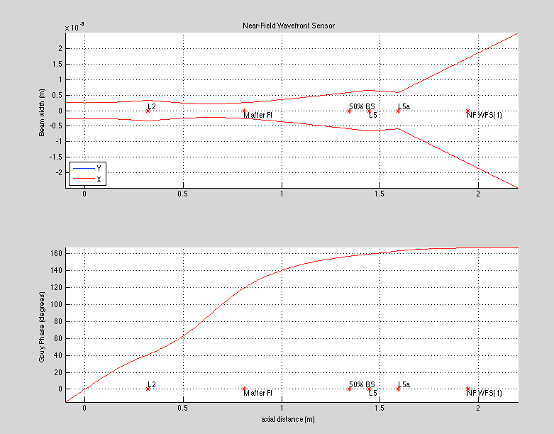
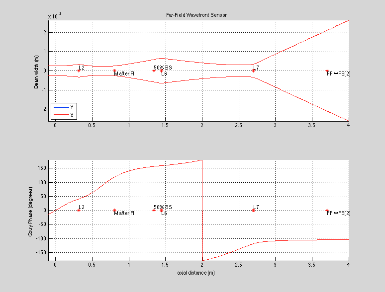
This is an adaptation of the mode-matching solution by Bram Slagmolen used for the OAT WFS in D1100607-v10, and shown in the attached plots. This is not the simplest possible solution, but it has the very desirable quality of having great flexibility with WFS placement while keeping 90 (+/-10) degree Guoy phase separation.
It is important to note that the nominal mode-matching solution used to generate this layout did not account for the beam quality issues. In theory, the input beam should have been small enough that the beam expansion properties of the layout would have been necessary to get a usable beam size on the WFS. If this ends up being an issue, the mode-matching can be modified to reflect reality.
WFSa1.jpg in the original entry was bogus (it was a copy of WFSb1). Attached is the correct one.
