First PRMI noise budget from the NB tool is attached.
Optical gain estimated from the openloop transfer function measurements are 5.5e3 W/m for MICH loop, 8.6e4 W/m for PRCL loop.
Power recycling gain estimated from this optical gains is ~ 3. This estimation was done by comparing the optical gain in simple Michelson and PRMI MICH.
Note that this estimation assumes perfect diagonalization of MICH and PRCL loop, but actually they are not diagonalized yet.
[Method]
1. Lock PRMI on sideband using REFLAIR_A_RF45_I_ERR and Q_ERR (see alog #10427).
2. Take OLTF of MICH loop and PRCL loop.
3. Keep it locked for a while to take feedback signal data (H1:LSC-MICH_OUT_DQ and H1:LSC-PRCL_OUT_DQ) for the noise budget. Data I used started from Feb 28 2014 18:25:00 UTC (local Friday morning).
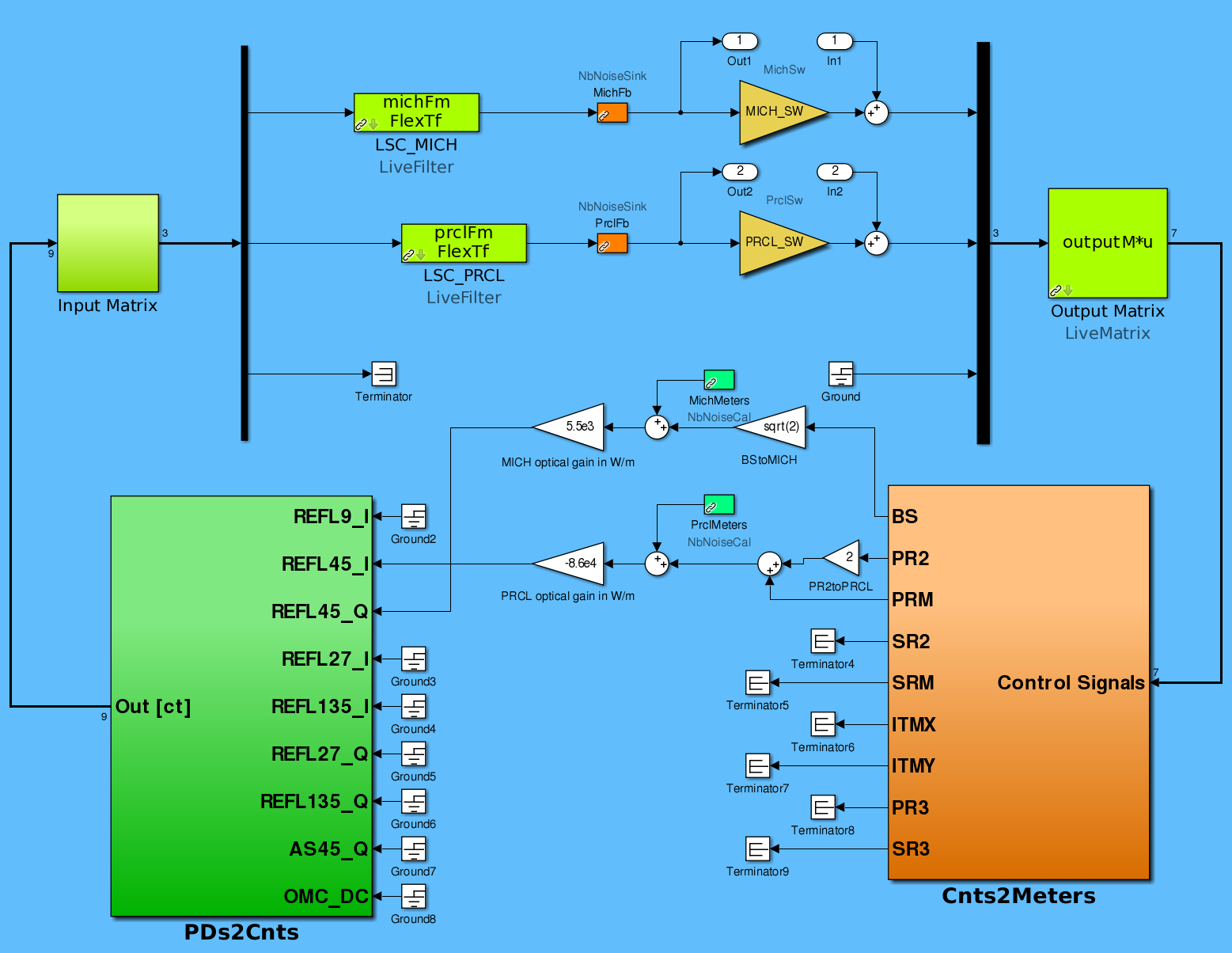
4. Use the NB simulink model to plot OLTFs. Change optical gain for MICH loop and PRCL loop to match those with the measured OLTFs. Here I assumed that the error signal from BS motion only appear in REFLAIR45_Q, and PR2/PRM motion only appear in REFLAIR45_I. See attached Simulink diagram I used. Optickle block is not used since we want to make the measurement based NB model. The model lives in /ligo/svncommon/NbSVN/aligonoisebudget/trunk/PRMI/H1.
5. Use the same model to plot noise budgets for MICH loop and PRCL loop. Sensitivity curve is estimated from the feedback signal data.
[Result]
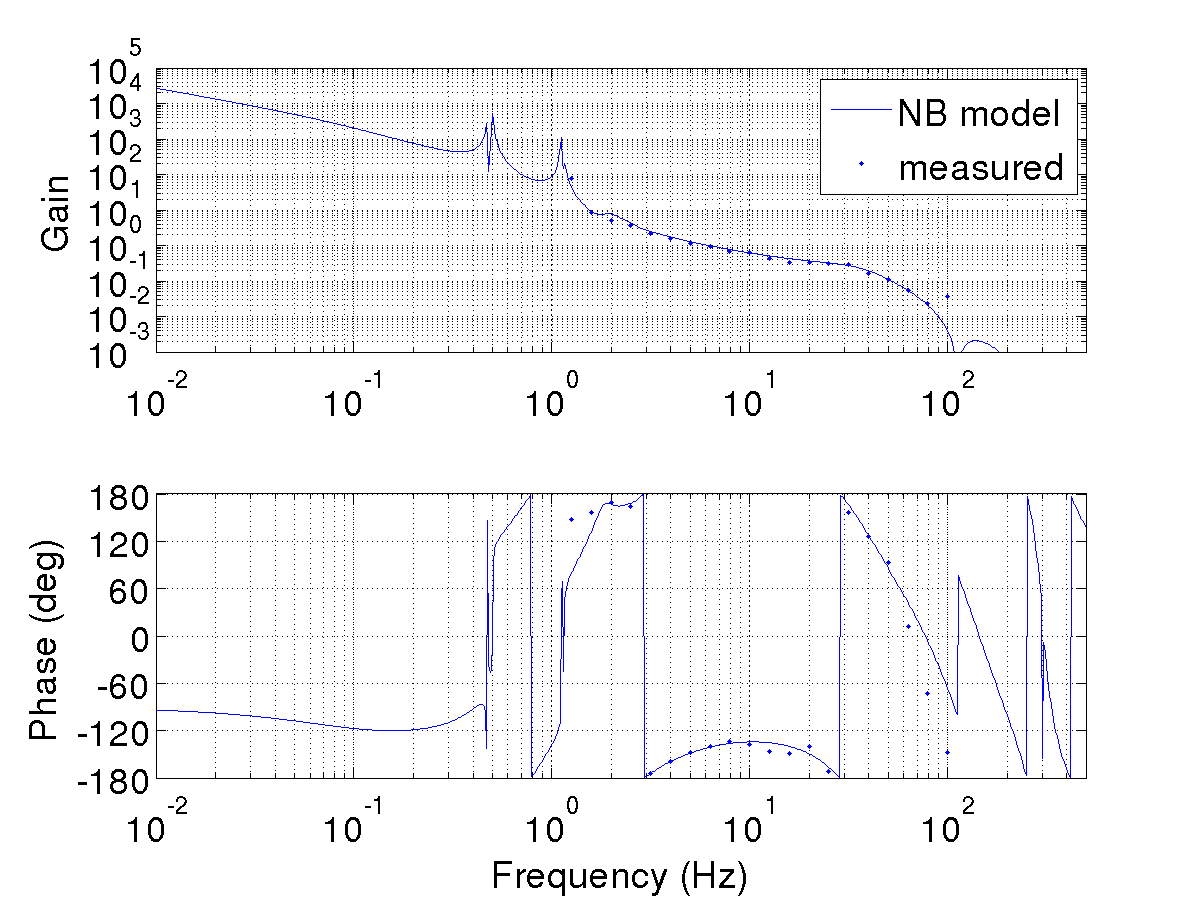
1. OLTF_MICH_1077647116.png: OLTF of MICH loop from the measurement and the model. UGF is ~6 Hz and phase margin is ~40 deg. For the model curve, optical gain of 5.5e3 W/m was used. The measurement and the model agrees pretty well.
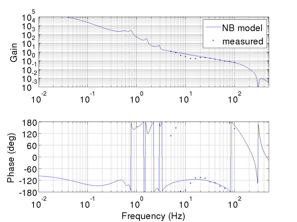
2. OLTF_PRCL_1077647116.png: OLTF of PRCL loop from the measurement and the model. UGF is ~60 Hz and phase margin is ~30 deg. For the model curve, optical gain of -8.6e4 W/m was used. The measurement and the model agrees OK except for the dip at ~13 Hz, which comes from closs coupling with MICH loop. This is because we only use BS for MICH loop, but BS also changes PRCL.
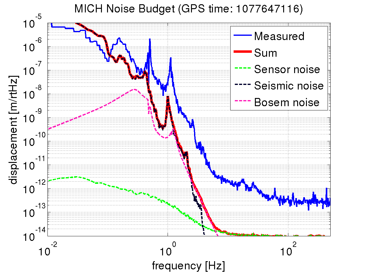
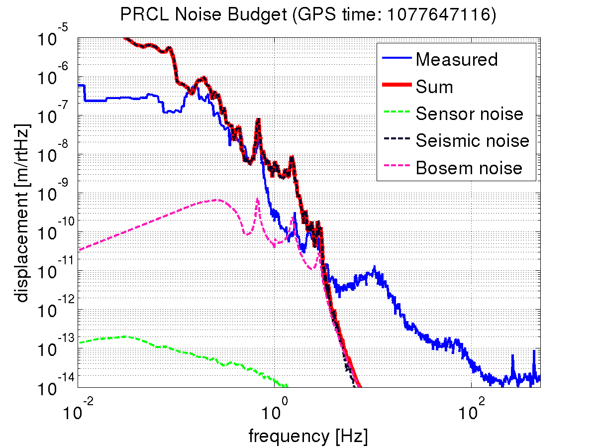
3. NB_MICH_1077647116.png, NB_PRCL_1077647116.png: Noise budget for MICH and PRCL loop. Note that seismic noise is not real (copied from LLO model). Sensor noise is currently not contributing very much. MICH motion is larger than PRCL motion (because of BS motion?).
[Discussion on PRMI optical gain]
1. Measured optical gain (from BS motion * sqrt(2) to REFLAIR45_Q) for simple Michelson was 1.9 W/m, including the cable loss (see alog #10213). The things changed in MICH loop for simple Michelson and MICH in PRMI are;
MI PRMI MICH
PD whitening gain 45 dB 0 dB
H1:LSC-MICH_GAIN 900 5
output matrix for BS 0.05 1
measured optical gain 1.9 W/m 5500 W/m
This gives overall gain ratio of MI/(PRMI MICH) = 1.3. Since the UGFs for simple Michelson and PRMI MICH loop was 8 Hz (see alog #10127) and 6 Hz respectively, this ratio is consistent.
2. Optical gain ratio between simple Michelson without PRM and PRMI should be approximately equal to the power recycling gain (PRG). However, since we did optical gain measurement for simple Michelson with PRM misaligned, measured optical gain will be smaller by factor of T_PRM^2. Thus, the ratio between simple Michelson with PRM misaligned and PRMI will be approximately Gp/T_PRM^2. So, estimated power recycling gain is;
Gp ~ 5.5e3/1.9 * 0.03^2 = 2.6
Designed PRG for PRMI is 58 according to LIGO-T1300954. Considering the closs-coupling between PRCL loop and MICH loop, this estimation seems to be an upper limit to the actual PRG (see below).
3. According to Optickle simulation in LIGO-T1300328, sensing matrix for PRMI sideband is
PRCL MICH
REFL 45I 3.4e6 2.5e3
REFL 45Q 6.4e4 1.3e5 W/m
So, simulated ratio between diagonal elements is PRCL/MICH = 3.4e6/1.3e5 = 26. Our optical gain estimation gives 8.6e4/5.5e3 = 16.
Considering the fact that we are ignoring the off-diagonal elements in the optical gain estimation, I think this is reasonable. For example, BS to REFL 45Q could be 1.3e5+6.4e4 W/m and 3.4e6/(1.3e5+6.4e4) = 18.
[Next]
- Measure PRMI sensing matrix, compare with the simulation, and use it in the NB model
- Update the simulink model so that it can handle off-diagonal elements
- Output matrix diagonalization for PRMI
- Include online seismic noise, frequency noise and intensity noise in the NB model
[Yuta, Evan]
From the above work, we can place a bound on the reflectivity of the locked Michelson (Rmich), and therefore also the finesse and the contrast defect.
From eqs. 4 and 6 of Freise and Strain's LRR paper, the power recycling gain in the plane-wave approximation is Gp = Tprm / (1 − sqrt(Rprm Rmich))^2. Using Gp = 2.6 and Tprm = 1 − Rprm = 0.03, we find Rmich = 0.82. The finesse is then pi * (Rpm Rmich)^(1/4) / (1 − sqrt(Rprm Rmich)) = 27.
Of the power incident on the Michelson, we lose 0.014 through ITMX, and 0.03 through ITMY. With our estimated Tmich = 0.18, this gives 0.136 leaving through the AS port.
Beyond the plane wave approximation, any mode mismatch of the light incident on the PRM will decrease the observed power recycling gain, and thereby decrease the estimated value of Rmich. The above finesse value is therefore a lower bound, and the above contrast defect is therefore an upper bound.