I re-measured BS and PRM actuation transfer functions in PRY configuration after plant inversion done on Mar 5 (see alog #10559).
It seems like we succeeded in BS and PRM balancing within ~8 % and MICH to PRCL coupling is expected to be supressed by factor of ~4, compared with using only BS as an actuator.
For the sensing matrix measurment, the effect of residual MICH to PRCL coupling gives ~6 % error for MICH to REFL45Q element and ~16000 % error for MICH to REFL45I element.
[Motivation]
Before measuring the PRMI sensing matrix, we wanted to estimate how good output matrix diagonalization is.
[Method]
1. Lock PRY and measure open loop transfer function. Compare it with the model to derive optical gain.
2. Measure actuator transfer function of BS and PRM from ISCINF to REFLAIR_RF45_I_ERR in PRY (using the same template used in alog #10450). Calibrate these TFs into m/counts with the optical gain derived in step 1.
3. Closed loop correct TFs measured in step 2. TFs should look like 1/f^2 at 1-300 Hz (see comments on alog #10450). Since output matrix for MICH in PRMI are set to (BS,PRM)=(1,-0.5), these TFs should be equal (see alog #10559 and table below).
-table of actuation efficiency (optic motion to interferometer length change in m/m)-
      PRY      PRCL      MICH

	BS    sqrt(2)  1/sqrt(2) sqrt(2)

	PRM   1        1         0
4. Calculate expected actuator TFs for MICH to PRCL coupling using the measured TFs. BS ISCINF to PRC length change will be half as that of PRY. BS-0.5*PRM gives the residual MICH to PRCL coupling.
[Result]
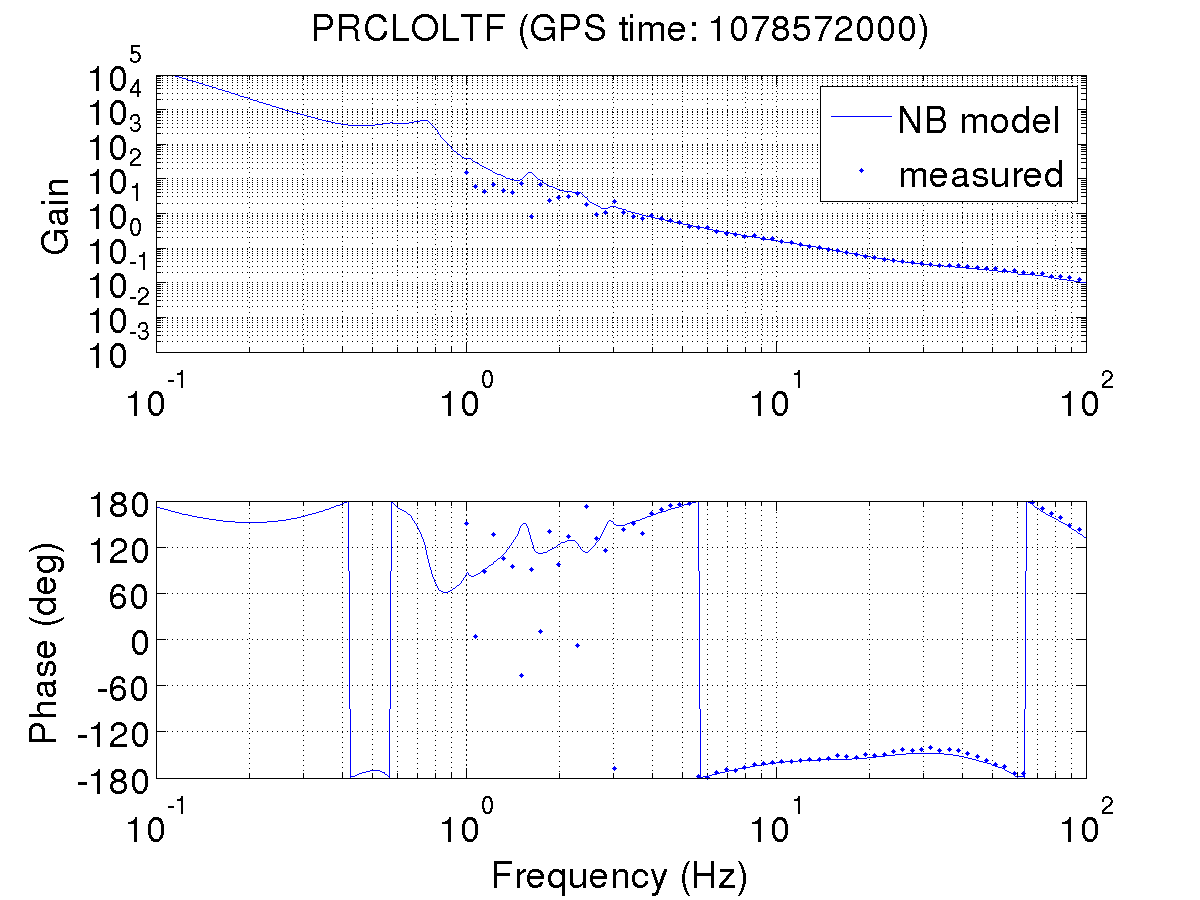
1. OLTF_PRCL_1078572000.png: Openloop transfer function of PRY lock. By comparing with the model, this gives PRY optical gain of 1.8 W/m. So, the calibration factor for REFLAIR_RF45_I_ERR in PRY is 4.7e11 counts/m. Note that this calibration factor includes losses in the PD signal chain (e.g. loss from long cable). Also, note that PRM suspension model was 30 % off from the measurement (see #10482; measurement = 0.77 * SUS model). This correction factor is included in the model to derive the optical gain.
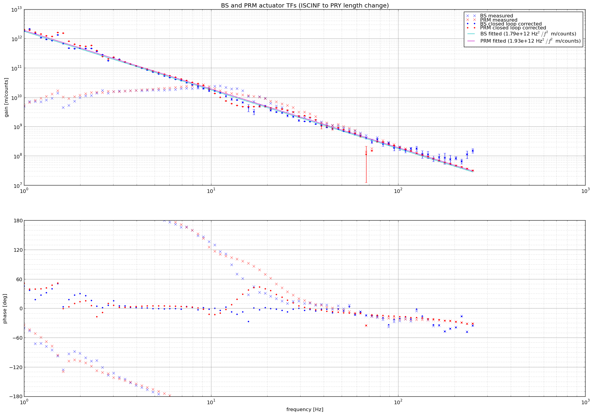
2. BSandPRMact_PRY.png: Measured actuator transfer functions for BS and PRM in PRY. x marks show raw measured TFs and dots show closed loop corrected ones. After closed loop correction, actuator TFs look like they follow 1/f^2. From the fit, BS actuator TF is 1.79e12 Hz^2/f^2 m/counts and PRM actuator TF is 1.93e12 Hz^2/f^2 m/counts for PRY. Considering the error bar from coherence and cavity build up fluctuation during the measurement, this 8% difference between BS and PRM is significant (error bars in TF magnitude are derived using the formula in alog #10506). We have done the balancing with the precision of ~10%, so this difference is reasonable.
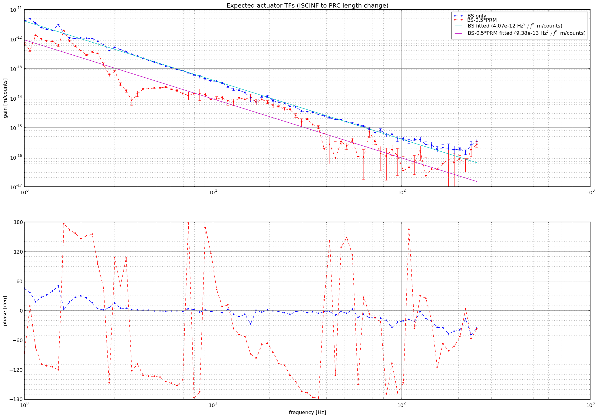
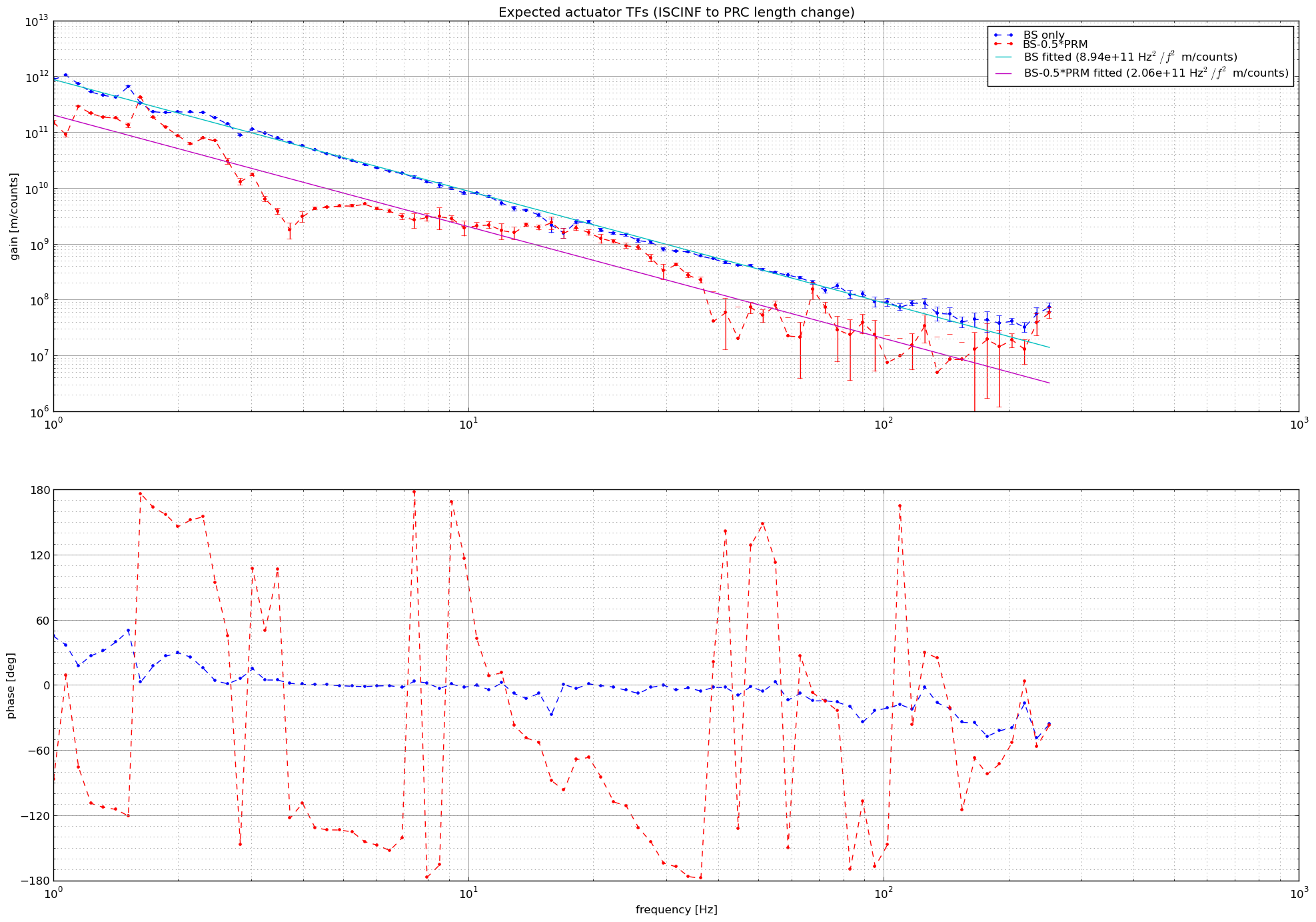
3. BSandPRMact_MICH2PRCL.png: Estimated MICH to PRCL coupling from actuator diagonalization. Blue dots show BS ISCINF to PRC length change and red dots show BS and PRM combined actuator to PRC length change. Fitted lines show that MICH to PRCL coupling is expected to be supressed by factor of ~4 by actuator balancing. We can improve this supression ratio a little bit by changing the gain balancing between BS and PRM by 8%, but it's not easy to improve more and prove we did more.
[Is this enough?]
This means that our MICH actuator (BS - 0.5*PRM) changes MICH length by 1.79e12 Hz^2/f^2 m/counts and PRC length by 2.06e11 Hz^2/f^2 m/counts. According to Optickle simulation in LIGO-T1300328, sensing matrix for PRMI sideband is
PRCL MICH
REFL 45I 3.4e6 2.5e3
REFL 45Q 6.4e4 1.3e5 W/m
So, the estimated effect of residual MICH to PRCL coupling to the sensing matrix measurement is;
MICH to REFL45Q element: 6 % error (= 6.4e4/1.3e5/(1.79e12/2.06e11) )
MICH to REFL45I element: 16000 % error (= 3.4e6/2.5e3/(1.79e12/2.06e11) )
If we ignore MICH to REFL45I element, which is hard to measure anyway, I think this is acceptable.
[Next]
- Update gain balancing factor between PRM and BS from 1/16 to 1/14.7 (FM5 in H1:SUS-BS_M3_LOCK_L)
- Update IQ demod phase in H1:LSC-REFLAIR_A_RF45_PHASE_R to minimize PRCL to MICH coupling
- Measure sensing matrix in PRMI
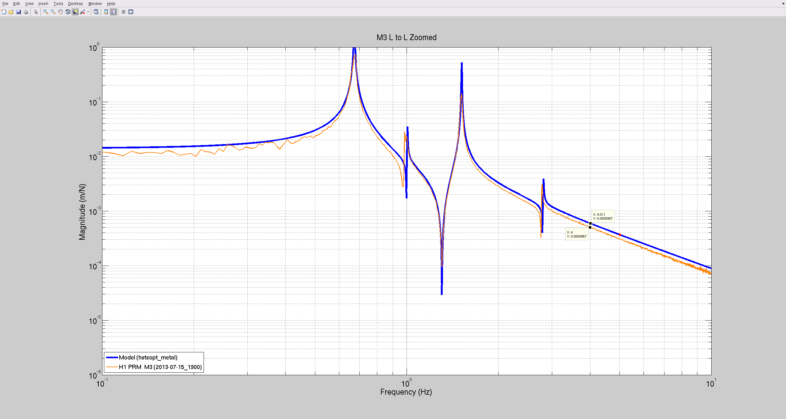
After talking with Yuta, I took a look at our PRM M3 to M3 transfer functions, measured with the osems as actuators and sensors, and compared it with the model. We see a factor difference of ~20% (model=1.18*measurement). This would mean the calibration error comes from the actuation chain (both of us are using T1000061 as a reference for calibrating actuation).
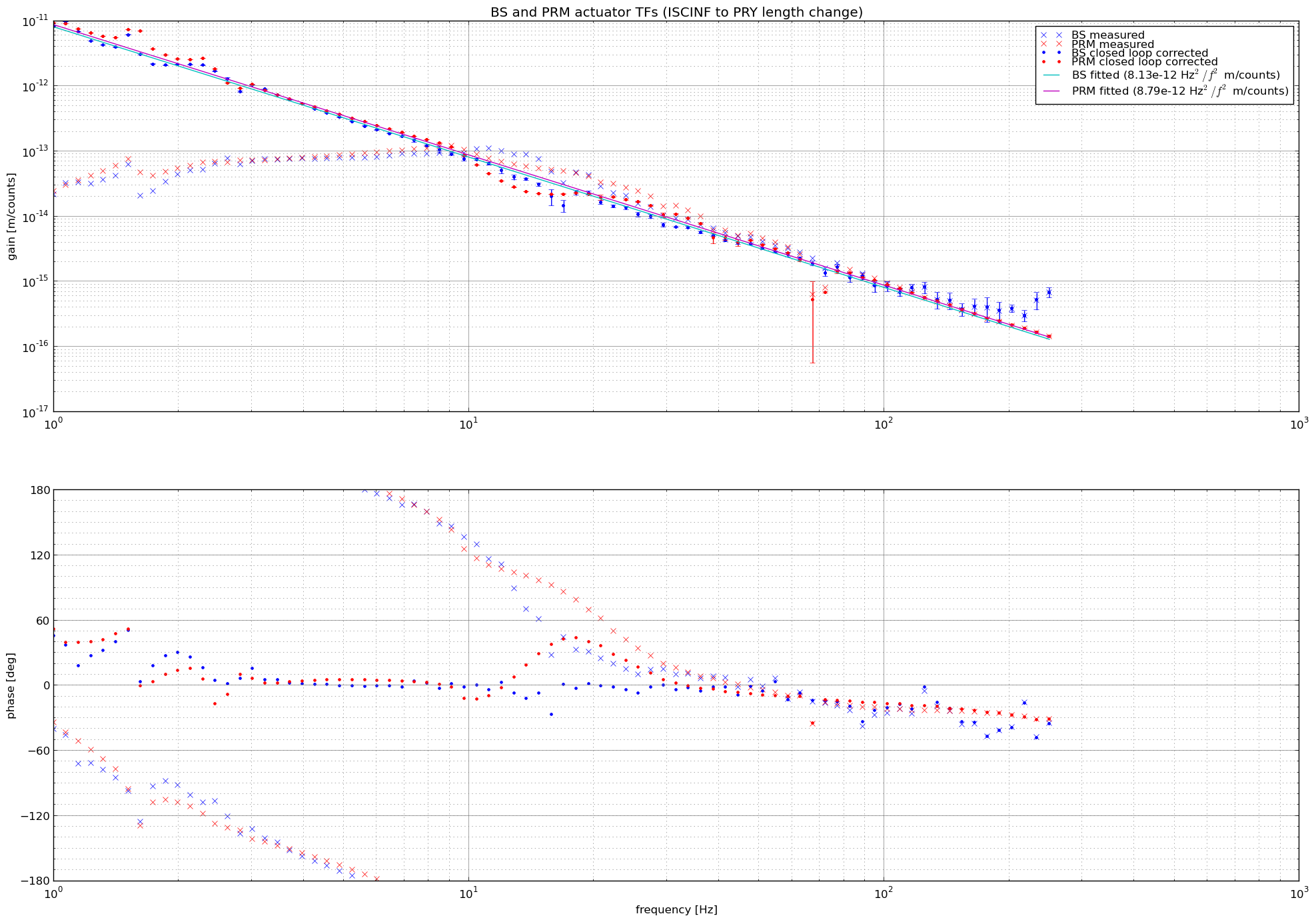
I did the calibration of the error signal wrong. The calibration factor 4.7e11 counts/m was correct, but I multiplied this number to the measured data in the script, instead of dividing.
Correct figures are attached. Actuator calibration from the fitting is as follows
BS to PRY: 8.13e-12 Hz^2/f^2 m/counts (half of this is BS to PRCL in PRMI)
PRM to PRY: 8.79e-12 Hz^2/f^2 m/counts (same as PRM to PRCL)
BS-0.5*PRM to MICH: 8.13e-12 Hz^2/f^2 m/counts (same as BS to PRY)
BS-0.5*PRM to PRCL: 9.28e-13 Hz^2/f^2 m/counts
Discussion about MICH to PRCL supression ratio and sensing matrix measurement error from actuation off diagonal element remain unchanged.
Also, note that my definition of MICH is one-way length difference between BS to ITMX and BS to ITMY. PRCL is PRC one-way length.
[Data and script]
Data and script used lives in ~/yutamich/BSPRMact/ folder.
./PRMdrive_complete.xml (dtt of PRM actuation TF measurement)
./BSdrive_complete.xml (dtt of BS actuation TF measurement)
./PRYoltf_complete1.xml (dtt of PRY OLTF measurement)
./BSPRMact.py (script for plotting and calibrating data)