(Corey, Greg, Mitch)
Stabilizing 200lb Masses
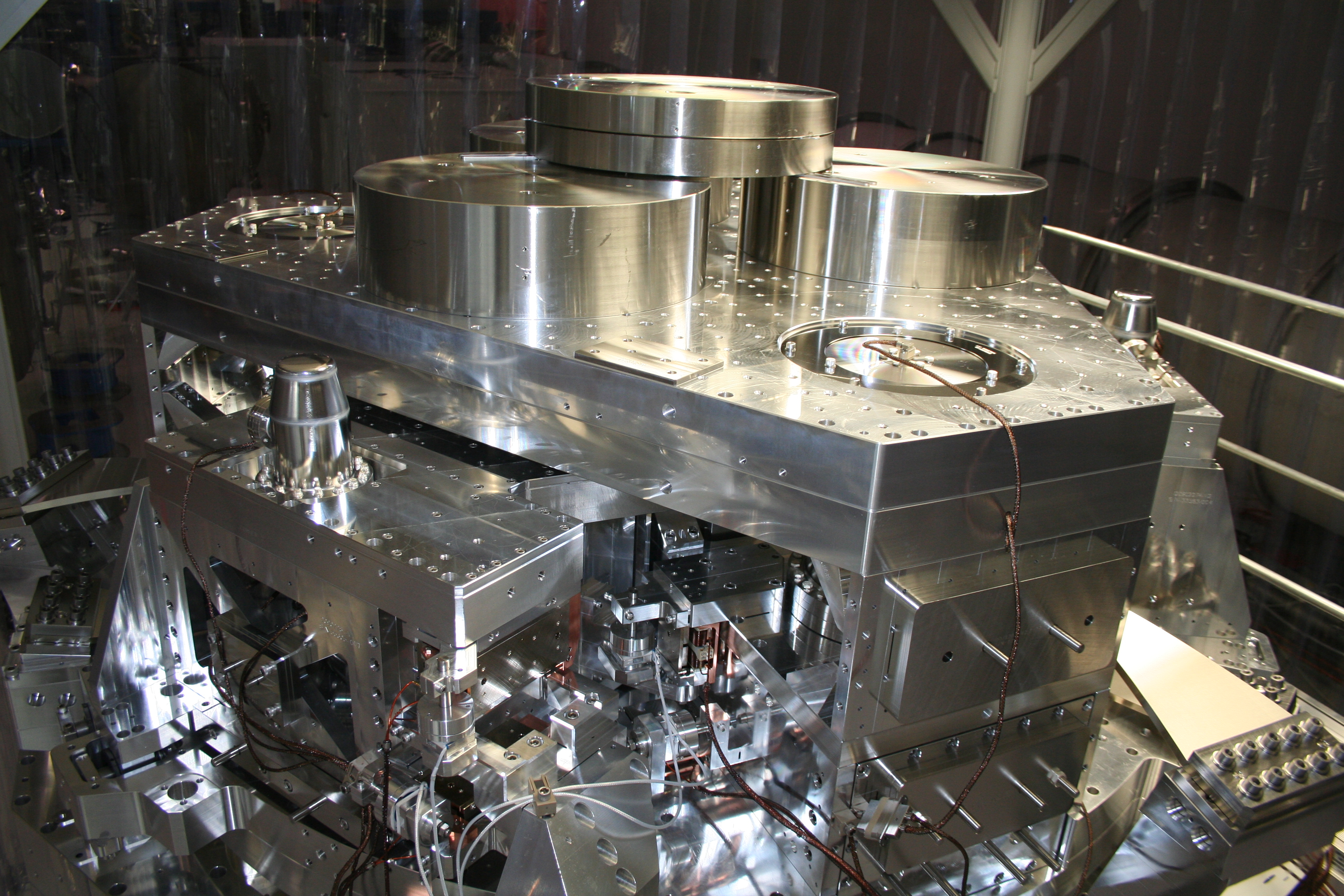
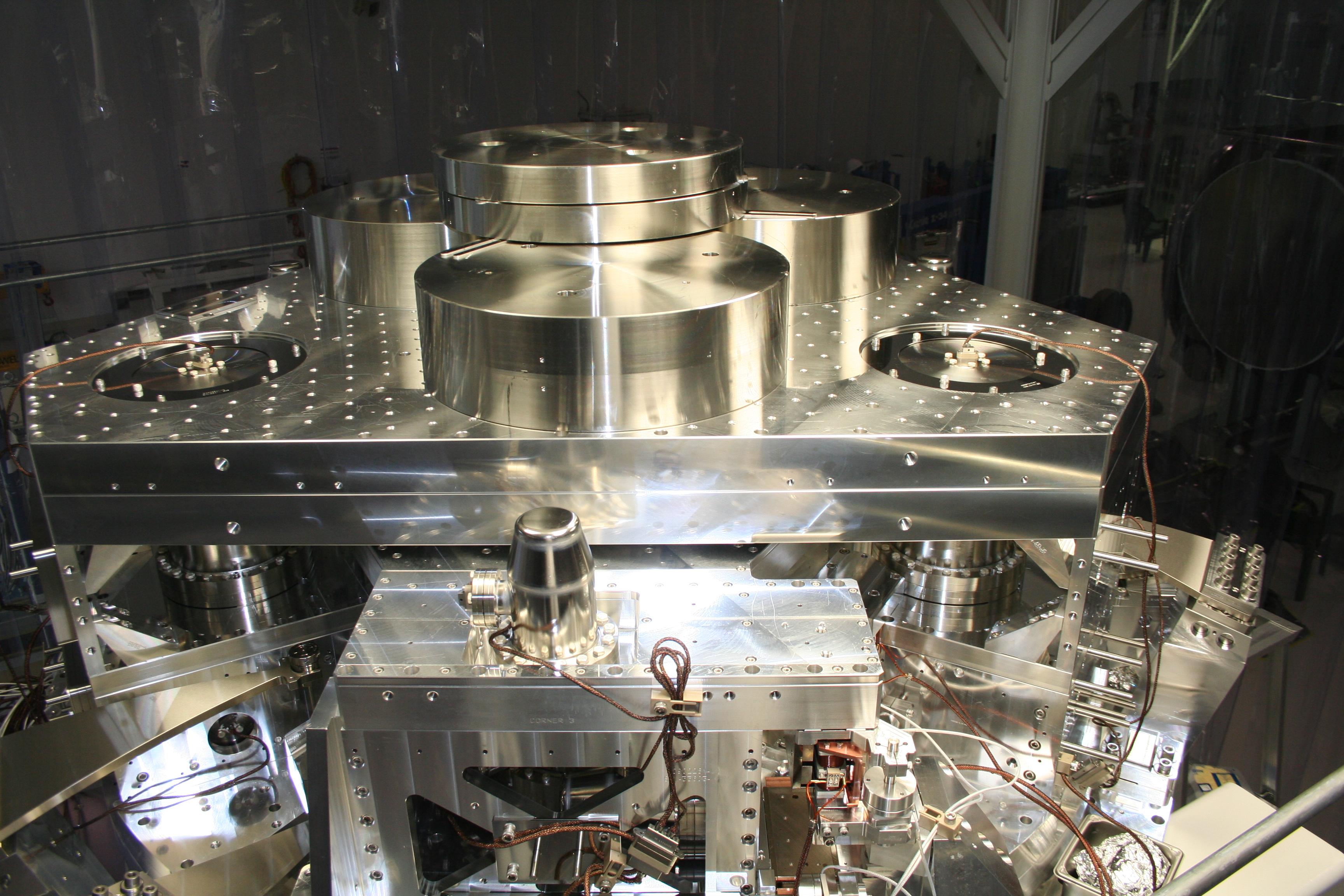
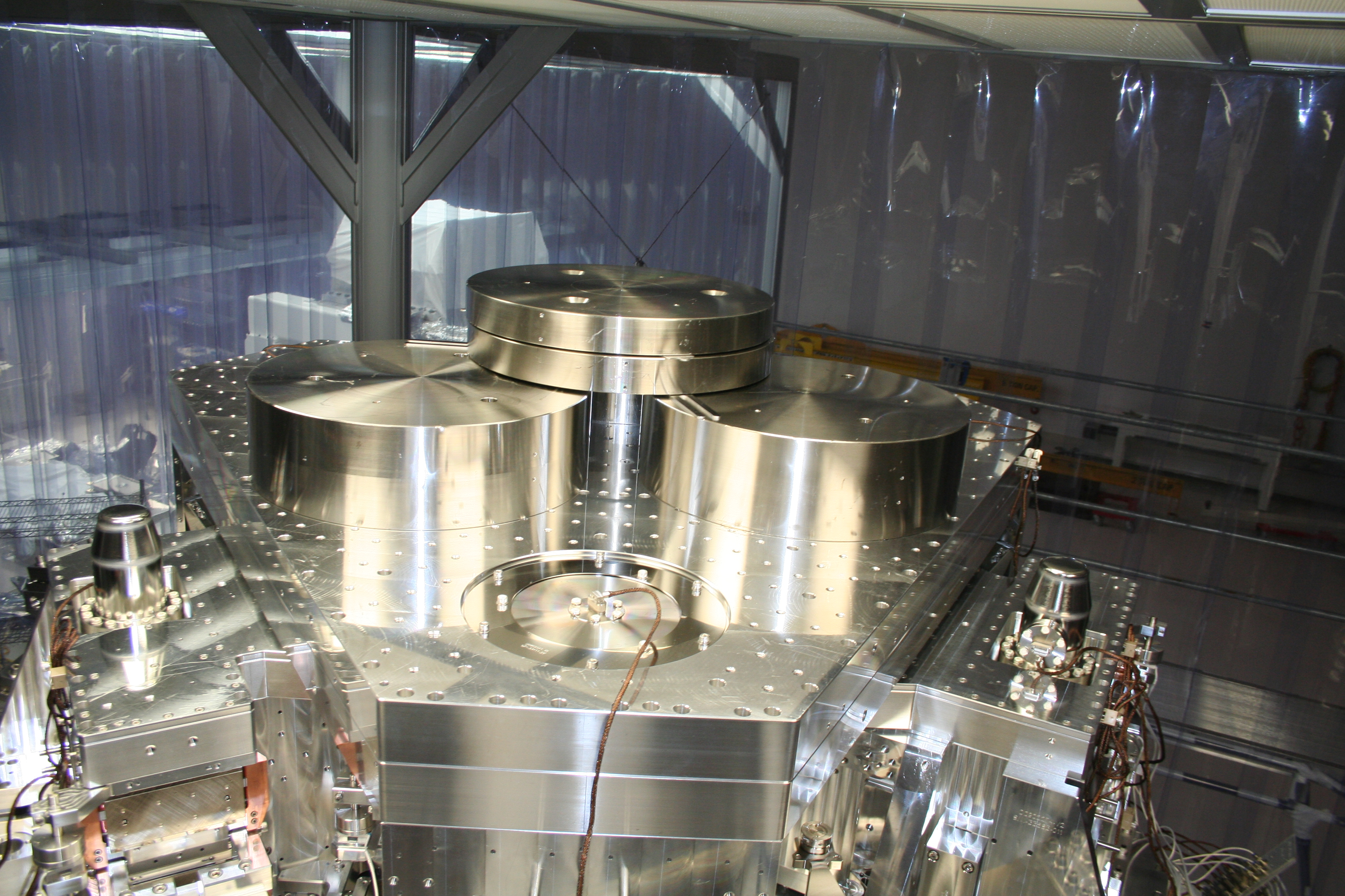
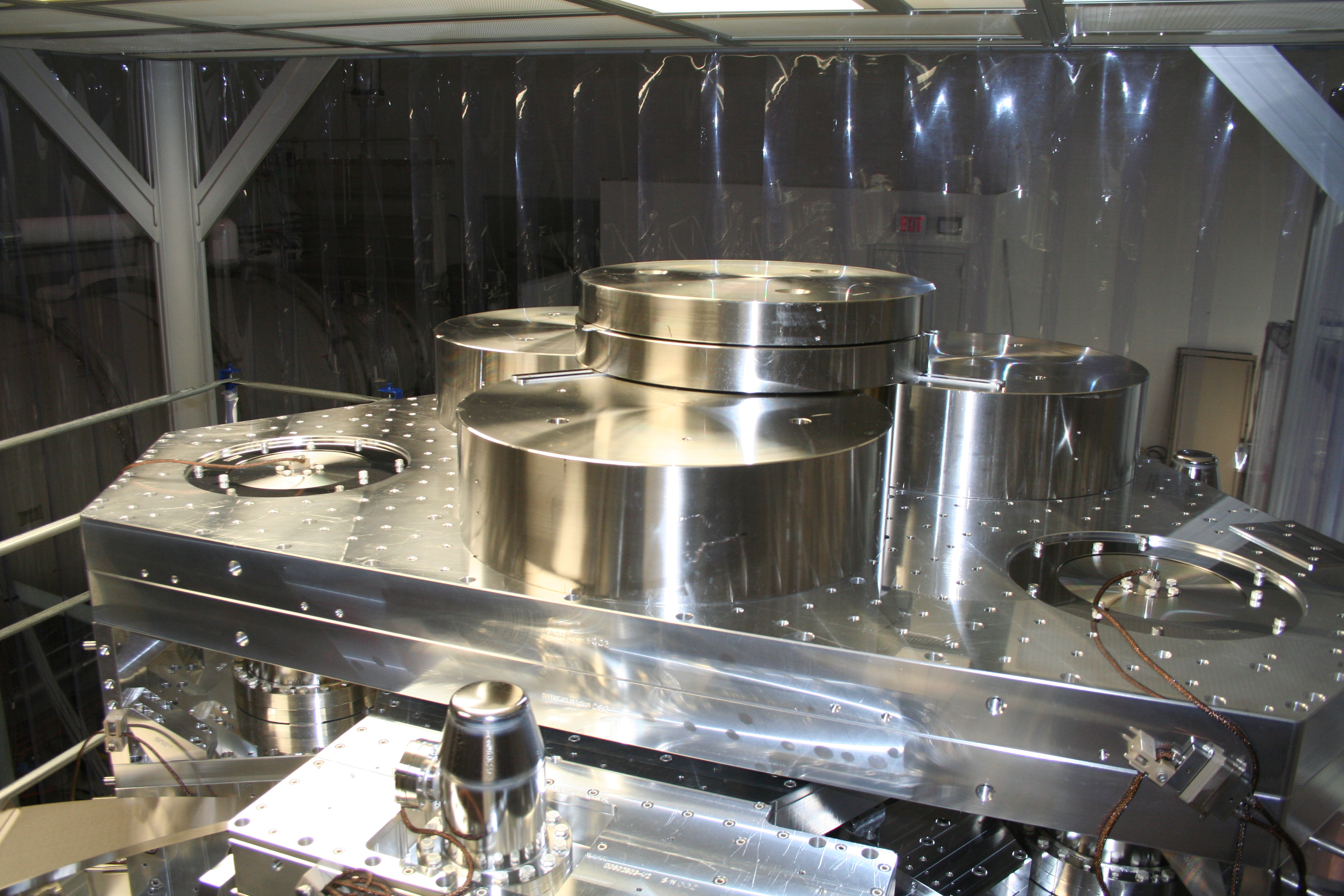
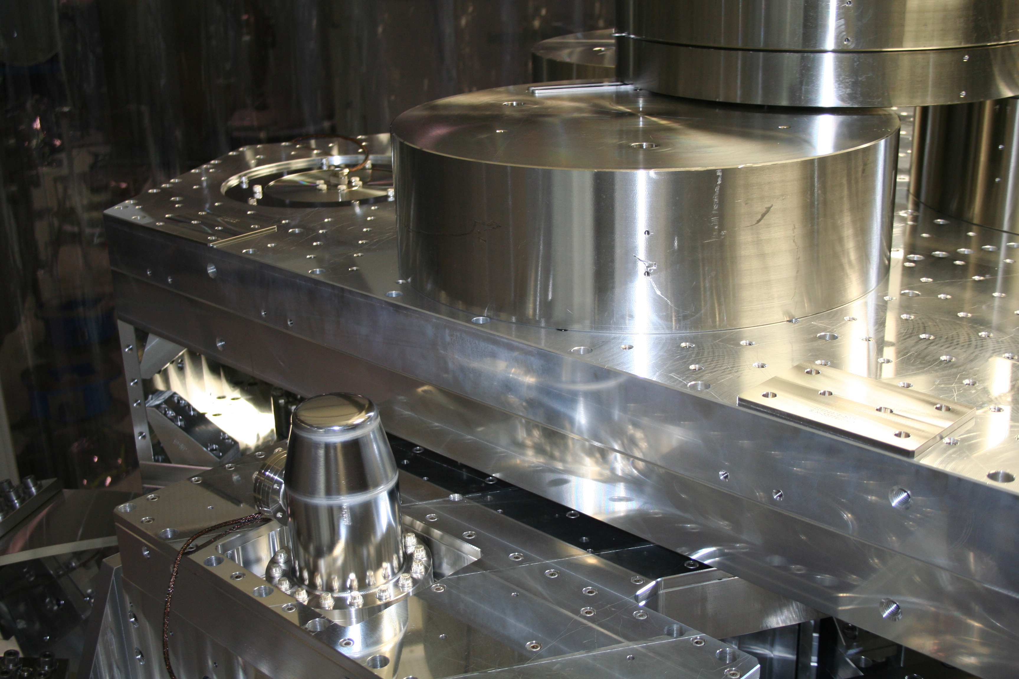
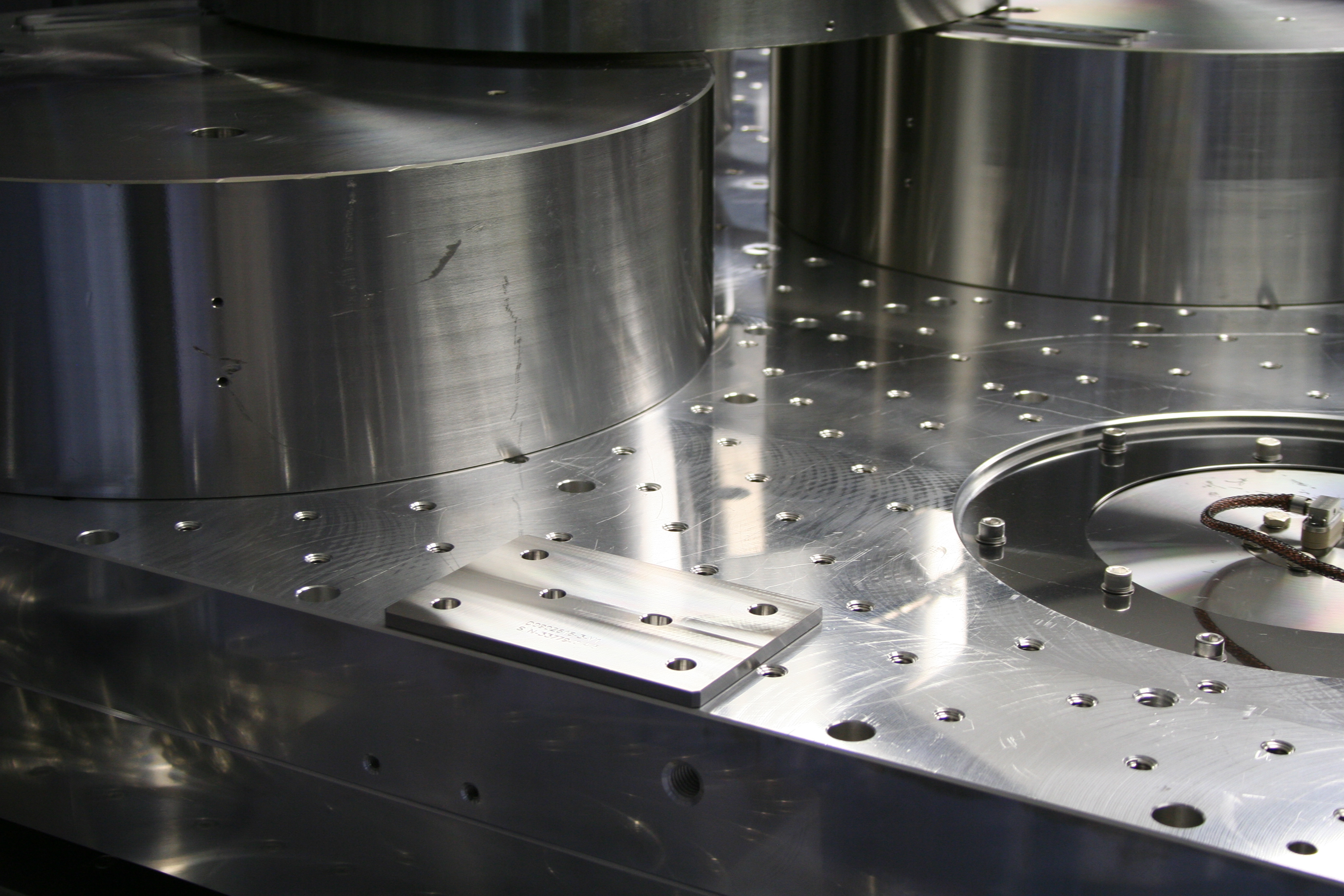
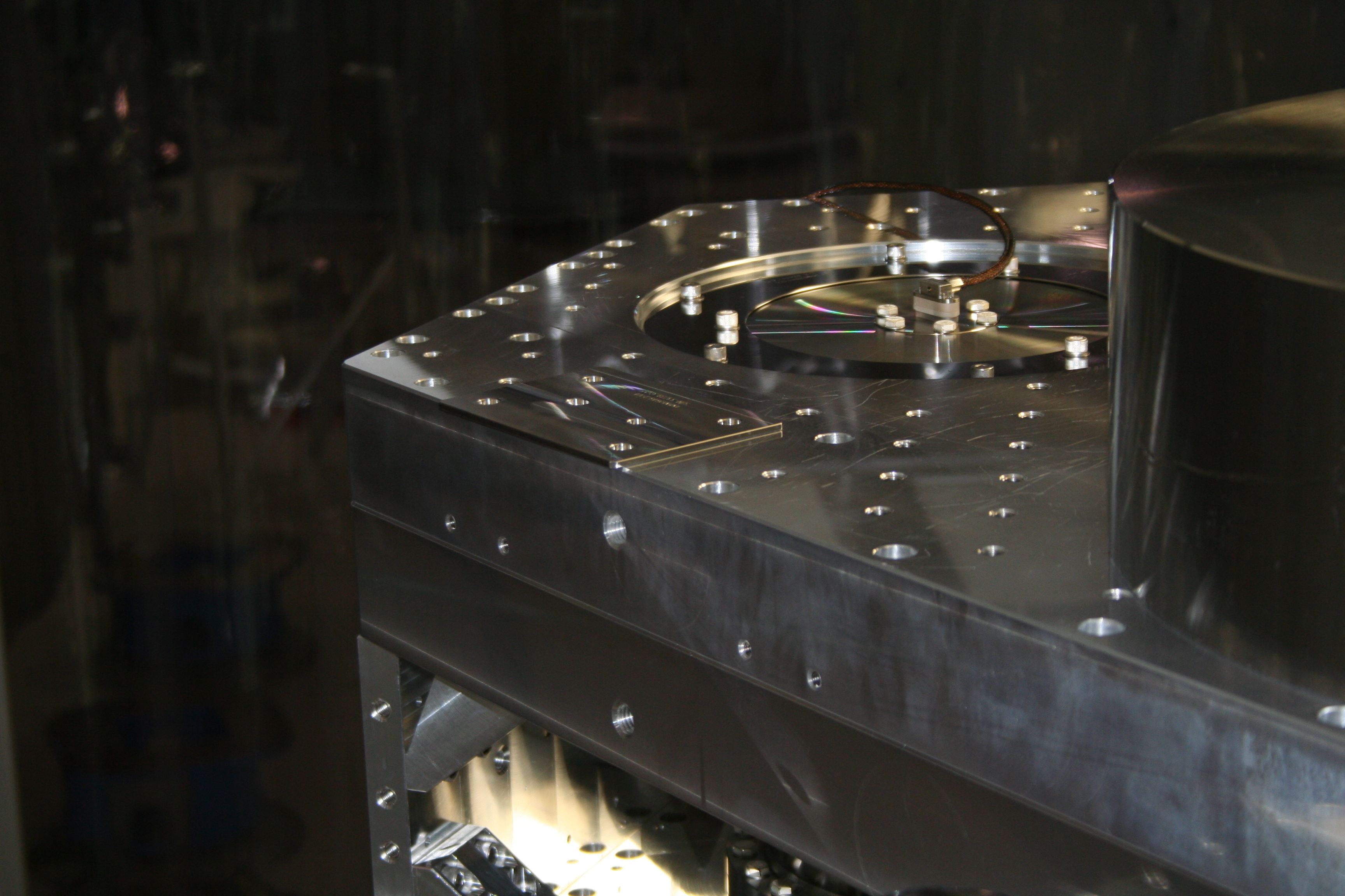
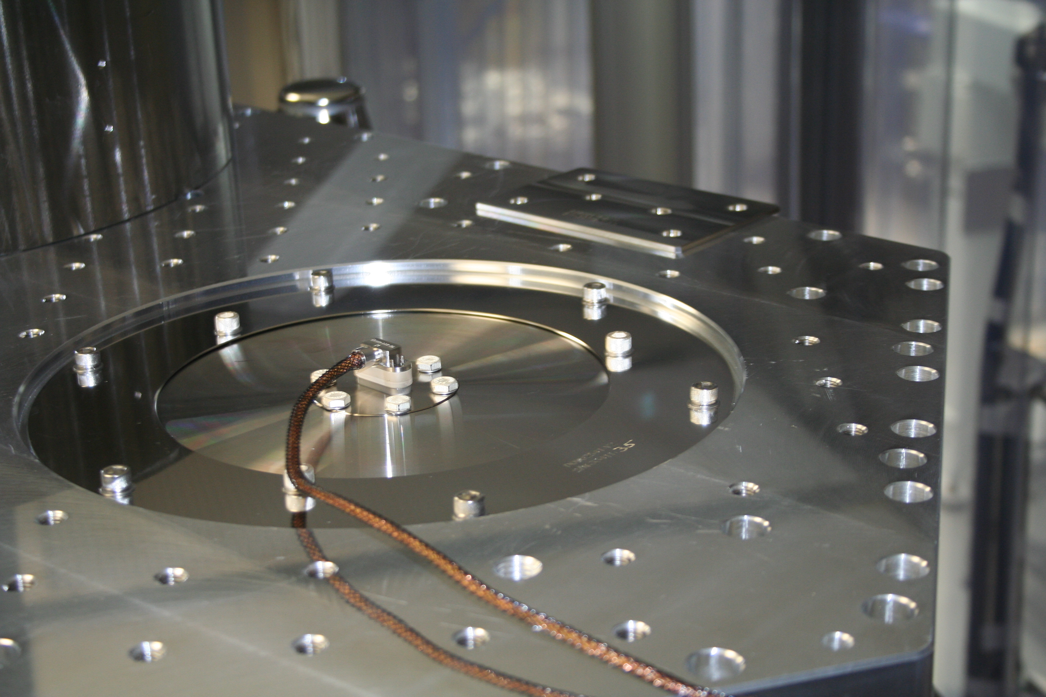
Vince noticed some ugliness in the transfer functions for #1 on the LVEA Test Stand. With the big (200 & 600lb Leg Elements) masses on top of the assembly being a possible suspect, we took a look at these masses. With the layout we have on top (see attached photos), we observed that the 200lb masses were not very secure on the table (none of these masses are bolted down, but we thought gravity would be enough to keep them secure); one could easily rotate or "teeter" these masses where they were.
So yesterday (Wed), we went in and lifted the 200lb masses and slipped shims under them so they would have 3-pt contacts under them. We did this for both 200lb masses (using two different types of shims for each mass; see photos). This noticeably secured the masses much better.
Notes:
1) These masses are a different set from the ones used for testing in the Staging Building.
2) This morning Vincent informed me the transfer functions haven't changed much. Perhaps we'll have to put shims underneath the 600lb masses next, or look somewhere else for noise issues.
Re-balance Of System
After work with the weights above and adding of shims, went about re-balancing of the ISI. With this sort of re-balance, we look at the Stage1-2 Vertical Capacitive Position Sensors (via Voltmeters plugged in to them). We adjust the payload until we can get the Sensors to have voltages of +/-0.500V (where a negative value means the gap is small...in other words the corner for this sensor would be low).
After several iterations, the best we could manage was the following:
Corner 1 (~crane east): -0.375 V
Corner 2 (~west): -0.340 V
Corner 3 (~south): -0.545 V
Corner 3 was the tough one, and this was the closest we could get to under +/-0.500V (see attached photo for locations of trim masses). Overall we're low (perhaps due to the added shims).
Noting Serial Numbers
Keeping track of sensors (i.e. Capacitive Position Sensors, GS13's, L4C's, Trilliums) is becoming a bit of a bear. Since we are ready to install sensors on BSCISI#2, and I didn't really have a grasp of where every sensor was, I went ahead and noted where sensors on #1 were and their serial numbers (well, only for those which had S/N's viewable.
For podded seismometers, I believe we are noting s/n's by the numbers scribed on the actual pod (vs the actual s/n of the seismometer inside or the "base" flange of the pod). Here is what we were able to note for s/n's on BSC#1:
L4C S/N's
Corner 1 Vert: 155
Corner 1 Horiz: 22
Corner 2 Vert: 151
Corner 2 Horiz: 152
Corner 3 Vert: 153
Corner 3 Horiz: 150
GS13
Corner 1 Vert: 76
Corner 2 Vert: 84
Corner 3 Vert: 98 *
* NOTE! This is the one which exhibited issues and needed to be opened up to repair it. It's good for testing, but needs to be replaced with another GS13 before this ISI is installed in the Vacuum System/BSC Chamber!)