aidan.brooks@LIGO.ORG - posted 10:50, Wednesday 23 April 2014 (11528)
TCSX install work - aligned up to polarizer
Aidan, Dave H, Matt H, Greg G.
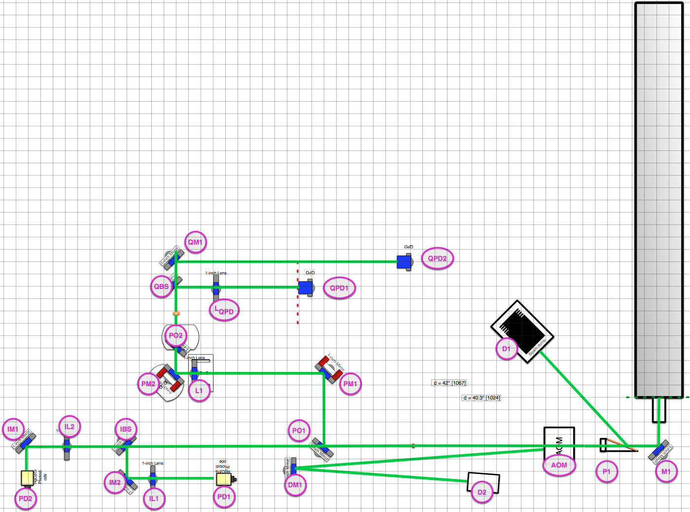
We aligned the X-arm CO2 laser through the first 40% of the optics on the table, including:
- M1: Beam is centered on this optic
- P1: The first polarizer dumps the majority of the s-polarization from the laser. With the laser running CW, 51.1W was transmitted, 121mW was reflected.
- D1: Dumps the s-polarization from the laser
- AOM: We aligned the AOM by driving it with maximum RF input and rotating the unit until the transmitted beam was minimized on a viewing card. This yielded ~80% DE.
- DM1, D2: dumps 1st order beam from AOM.
- PO1: 99% reflector. Transmitted beam goes to ISS photodiodes
- IBS, IM2, IL1, IL2, IM1: All ISS optics aligned
- PD1, PD2: Not yet installed
- PM1, PM2: Beam steering picomotor mirrors - beam is centered on these optics
- L1: 6" focal length lens (part of telescope to image beam onto the masks)
- PO2: 99% reflector.
- QBS: 50/50 beam splitter for beam positioning
- QM1, LQPD: Lens and mirror aligned
- QPD1, QPD2: installed and beams roughly centered on these sensors. We've not confirmed the output from these yet.
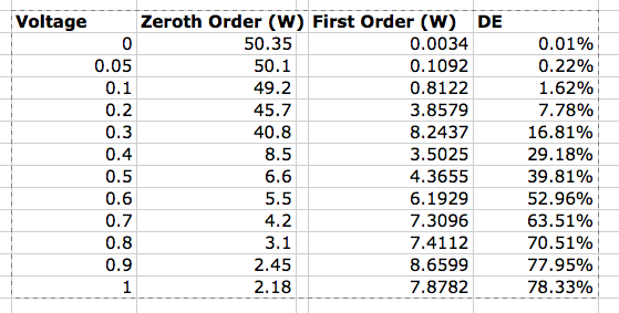
We measured the DE of the AOM as a function of applied voltage (via the front end model). The results are posted in the table below. The AOM is quoted as having a maximum DE of ~85% at the exact Bragg angle.
The Y-arm table laser is ready to test on Wednesday.
Images attached to this report
Non-image files attached to this report
