Mark B. and Gerardo
Yesterday (4/22/14) Gerardo and I measured the vertical mode Q of the OFIS for three different positions of the ECD block to try to get the Q in the specified range of 25-30.
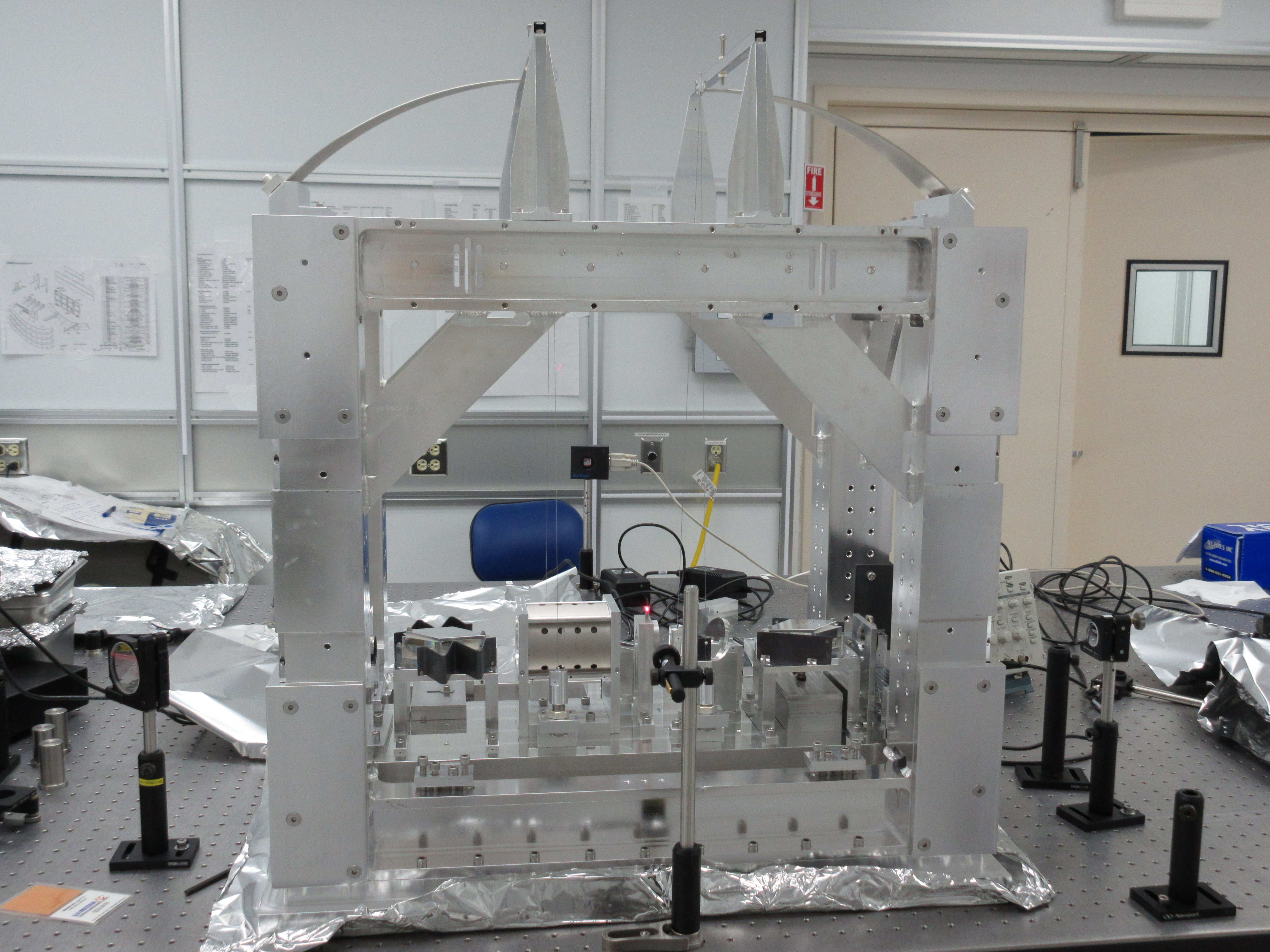
The OFIS was set up on the optical bench in the H2 laser enclosure. The ECD block sits on a tray below the payload which is supported by four groups of vertically pointing screws at accessible positions around the edge of the structure. Gerardo had earlier attempted to set the ECD block at the nominal height using the spacer tool provided but found that this was too high and caused interference. He therefore lowered the block until it was just barely clear plus approximately an extra two turns of the 1/4-20 screws. This was our starting point for further adjustments.
To measure the vertical Q, we used the laser pointer and QPD from the monolithic violin mode setup and used a convenient screw on the top of the payload to partially block the beam. We displayed the "pitch" output of the QPD box on a digital oscilloscope with a 1 sec/div timebase and photographed the screen to capture the data. I read off the peak positions with GraphClick, and worked out the logarithmic decrement and Q with Mathematica.
For the initial position, the Q was 10.7. We lowered the ECD by one turn on all the screws and got Q = 18.9. We lowered the ECD another half turn and got Q = 23.3. Finally, today (4/23/14) we lowered the ECD another 3/4 turn and got 27.8, which is in spec.
Attached is a JPG of the setup, a PDF of all the screenshots, and for the fourth and final run, the Mathematica notebook, PDF thereof and the raw data.


We went back on Friday 4/25 and used the same method to measure the longitudinal (parallel to the OFI beam axis) and transverse mode Qs. For the longitudinal measurement we were able to keep the laser in almost the same position, just clipping a different edge, but for the transverse we had to send the beam on an odd diagonal path clipping one corner and then passing through the hole in the beam dump at the end (see photo). The results were
L: 21.3
T: 15.3
V: 27.8 (from 4/23, above)
The spec is <30 per T1000308-v1, p36, so these Qs look good and we propose to leave it like this.
I measured the gap between the copper plate and the magnets, 4 mm and all 4 corners.
Per request of Jeff Kissel, I extracted the frequencies from the data of 4/23 and 4/25 for the final configuration of the dampers: