stefan.ballmer@LIGO.ORG - posted 12:04, Monday 05 May 2014 (11710)
ETMX TOP / UIM relative actuator adjust
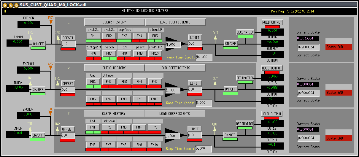
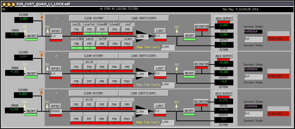
Sheila, Arnaud, Stefan

Based on the model (both the sophisticated official, as well as a simple 4-mass, length only one) the transfer function ratio
(TOP_L-to-TST_L)/(UIM_L-to-TST_L) is given by a simple pendulum resonance, namely the resonance of the top mass, assuming ass other masses are locked down (divided by the spring constant strength between TOP and UIM).

Since we had a very good measurement of the TOP_L-to-TST_L transfer function below 1Hz, we trusted those poles and zeros, and simply updated the UIM inverse plant filter with the corresponding <1Hz poles and zeros of the TOP inverse plant.

Next I copied the top mass blendLP to the UIM LOCK bank, and added a gain of -1. this allowed my to drive the nominally same signal through TOP and UIM, with opposite sign. Then I fine-tweaked the relative gain (and additional factor of 1.255 for the UIM drive), getting a drive signal cancellation of -39dB at 0.31Hz. THe same gain setting still gave me a cancellation of -26dB at 0.91Hz.

I now trust the TOP/UIM blended actuator - onwards to the ESD!

Attached are snap shots for the LOCK filter banks. (The UIM - the one with the gain of 1.255 - has the wrong title - the MEDM needs to be updated.)
Images attached to this report