jeffrey.kissel@LIGO.ORG - posted 21:19, Tuesday 13 May 2014 (11874)
ESD Linearization added to H1SUS ETMs
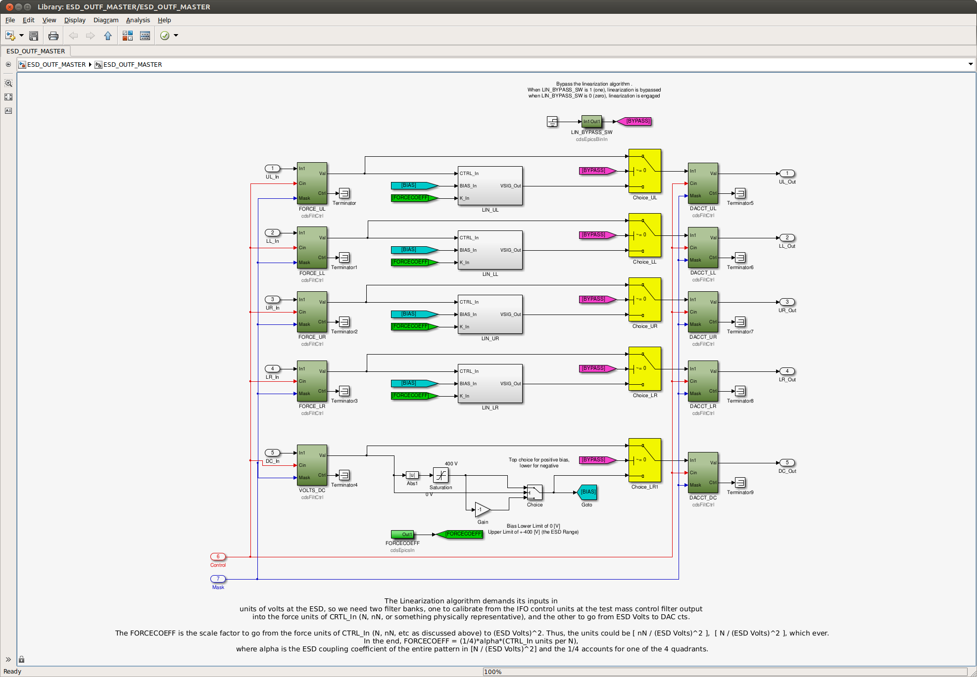
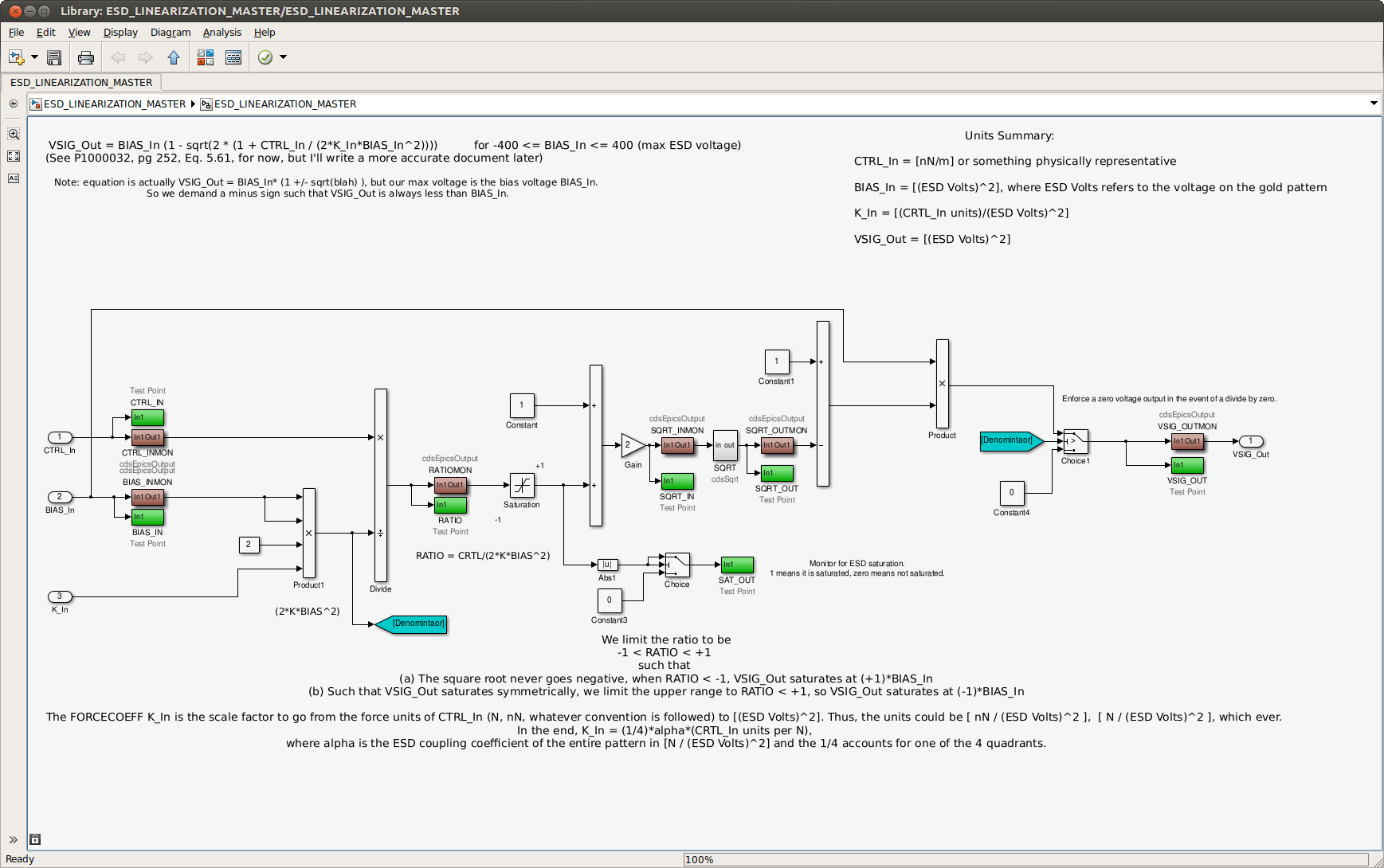
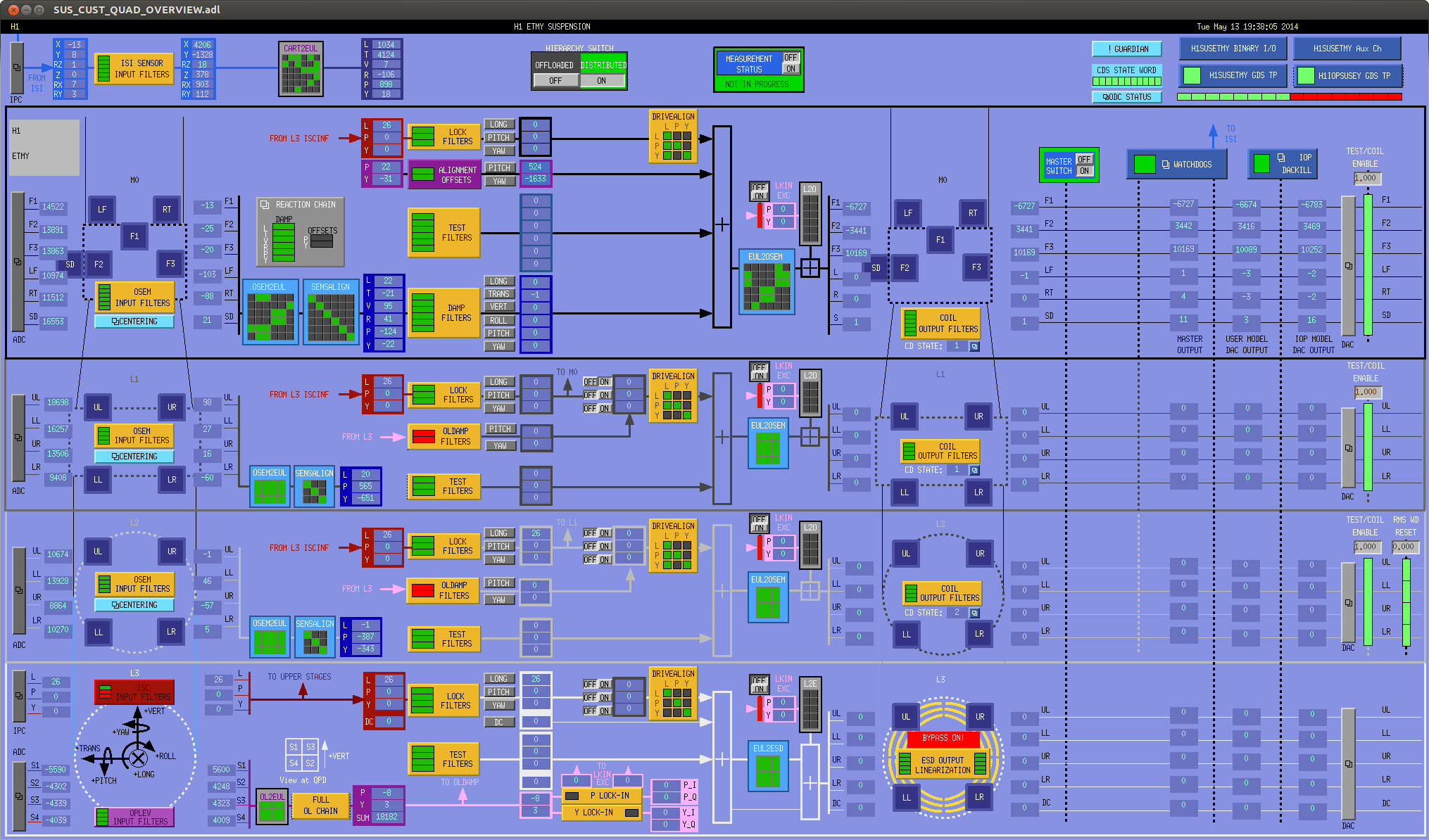
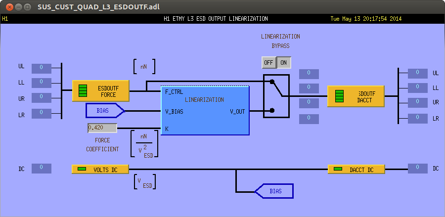
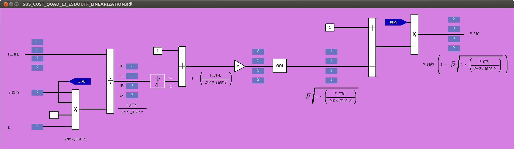
J. Kissel

I've added the linearization algorithm to H1 SUS ETMX and ETMY, as sketched out in T1400321. I have not tested its functionality, since folks needed both ETMs to get back commissioning / exploring ALS DIFF, but I've created the first-draft MEDM screens, and filled in a few of the gains such that we can start testing tomorrow morning. The algorithm has been installed with a bypass, which will be engaged for the night on both ETMs.

Three notes of importance the expert user:
(1) For Stuart: I've installed these modifications into the QUAD_MASTER.mdl library part (where the only change was to replace the ESDOUTF with the ESD_ESDOUTF_MASTER, and change the DAQ channel list to store the new version of the ESD Basis excitation channel names), assuming that we'll need to propagate this is to all QUADs, but I have not committed the changes to the SVN. I did have to change the
ESD_OUTF_MASTER.mdl
to include the bypass, this *has* been committed to the repository, since LLO is still using a more stripped down version of the algorithm, unhooked from any library parts (see LLO aLOG 12390).

(2) For Dave: This is a "time-bomb" for the QUAD ITMs, given that they use the changed QUAD_MASTER, but haven't been re-compiled. However, the change involves no top-level connection changes, so the ITMs should compile happily. I've edited the generic MEDM screens, so whenever the ITMs are recompiled, reinstalled, restarted, and restored, they'll just inherent the change. Also, we don't use the ESD on the ITMs, so no one cares at this point.

(3) For Kiwamu/Stefan: As described in T1400321, this algorithm assumes that we want to operate at 1/2 the maximum force, and hence there will be a DC value of V_BIAS * (1 - sqrt(2)) always output on the V_SIG channels. Eventually, we want to be able to ramp this bias over to the bias electrode for noise considerations, such that the individual quadrant voltages have a mean of 0, and only AC signals. However, currently, this algorithm can't support this.

------------
Details

First assumption: we never use the ESD for angular control. Otherwise the linearization process will get messy (even more messy than it already is) really fast.

Gain/units allocation:
The linearization algorithm is based on using physically intuitive units: force units of desired control signal (in some order of magnitude version of [N]) on each quadrant, voltage on the bias electrode [V_ESD], and a conversion factor, or force constant between them [N / V_ESD^2]. In order to obtain such a convention, we need to surround the algorithm with buffer filter banks that change the calibration in the the appropriate units in and out of the algorithm.

As such, we have three new filter banks (follow along with SUS_CUST_QUAD_L3_ESDOUTF.png):

H1:SUS-ETMX_L3_ESDOUTF_FORCE -- coverts the L3 stage control voltage into force units. Since the combination of the DARM filter and the Hierarchical Design filters take out all of the frequency dependence prior to this input, we only need to convert this into force units at DC. Since ISC has done the work to convert their control signal into [um], we only need the QUAD model to get the [N/m]. Such that we can see the force coefficient on an MEDM screen, we choose the nano order of magnitude, [nN], and the gain in this bank should be
(1 / 0.0026 [m/N]) * 1e-6 [m / um] * 1e9 [nN / N] = 38462 [nN / um]

H1:SUS-ETMX_L3_ESDOUTF_VOLTS_DC -- converts request DC bias into voltage on the ESD bias electrode [V_ESD]. This should also be a frequency independent gain, the value which depends on the preference of the user input. People seem to prefer to have the DC BIAS already in [V_ESD], so this bank will remain and empty pass-through for now.

H1:SUS-ETMY_L3_ESDOUTF_DACCT -- these convert each requested voltage back into DAC counts, since these are the fundamental units of the DAC, which we know saturates at +/- 2^17 [ct]. Each ESD driver channel should be identical, and frequency independent (up to ~2 [kHz], a pole for which we don't compensate), so again, the filter is just a DC gain. That gain should be
ESD driver gain * DAC gain = (1/40) [V_DAC / V_ESD] * (2^18/20) [ct / V_DAC] = 327.68 [ct / V_ESD].


And finally, the final input to the linearization algorithm needs the unit conversion from force to volts squared, i.e. the force coefficient,
H1:SUS-ETMY_L3_ESDOUTF_FORCECOEFF.
From G0900956, the force coefficient for the entire four quadrants is 4.2e-10 [N/V^2] (where the [V] in the denominator are the same [V_ESD] as above). We want the force coefficient for each quadrant, so we'll divide by 4 and then scale to the up appropriate order of magnitude:
4.2e-10 [N/V^2] * 1/4 [1/nActs] * 1e9 [nN / N] = 0.105 [nN / V^2]

Stay tuned, I'm sure this all change tomorrow once I get things working, and I have a discussion on this gain allocation with more people.
Images attached to this report