
REMOVE SEARCH FILTER
SEARCH AGAIN
Search criteria
Section: H1
Task: DAQ
WP 13326
Dave noted we lost Beckhoff channels yesterday around 6PM. Daniel logged in and confirmed terminals missing in Corner Chassis 4. The third EtherCAT coupler was replaced.
Chassis Serial Number S1107450
D. Barker, F. Clara, D. Sigg
I updated and restarted the frame writer on h1daqfw2 yesterday at 1:37pm and today at 3:04pm localtime.
I updated and restarted the experimental framewriter on h1daqfw2 today around 2:20pm localtime today. This was to verify some new code still produced identical frames.
Upgraded the main slow controls software to add some calibration features for CHETA.
Restarted the slow controls system to fix an issue with the CHETA motor stages.
We had some hiccups in our end of day daqd restart.
1. There were duplicate channels between the h1susb13 and h1susb2h34 models. We are not sure how these got through, the daqd should have crashed on startup with an error message. We found this as it caused issues on the test framewriter on h1daqfw2.
2. After Oli removed the old block from h1susb13 we found that there were some GDS broadcaster channels that were dropped that probably shouldn't be. We removed them from the broadcast list in order to get the daqd to run. Listing the channels here so that they can be added back in tommorow:
After looking through the code, this is an old bug. It has been fixed for a while. The daqd had not been updated with the rcg for a long time due to no feature changes.
We should do a daqd package upgrade next week.
Dave, Jonathan,
We restarted the daqds today, daq1 leg at 15:56, and the daq0 leg at 16:01 localtime.
This was in support of two workpermints
12945 - monitoring the daq kafka connector as we push data into the NGDD system in ldas (NGDD = next generation data delivery)
12946 - TJ added two guardian nodes to help manage JM1 and JM2
Added the cabling for the new whitening concentrators. This also required a software upgrade.
The following QPD whitening channels were affected:
Instead of 4 x 8-bits, only 1 x 8 bits are used and all 4 segments are switched simulatanously. There is no change in the whitening interface for these QPDs, since the software already tied the segments together. The only change is in the readnback bits where only the last 8-bits are still significant.
This allowed us to add the whitening for the JAC WFS as well as dewhitening for the JAC PZT driver.
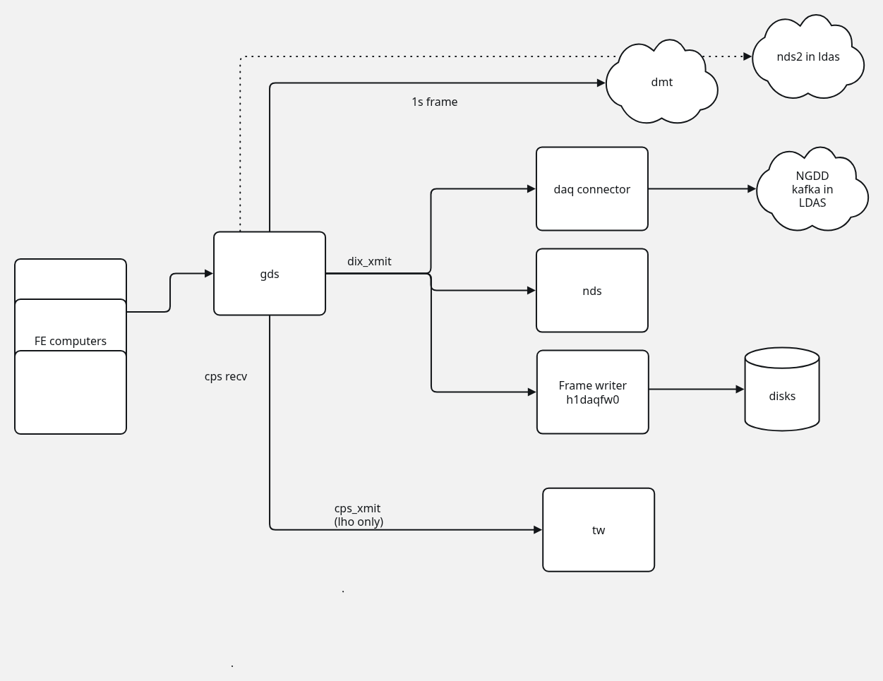
We have been seeing a low rate of data drops with the frame writer serving as both the frame writer and the data concentrator for the DAQD 0 systems. This work is to try an alternate configuration. Moving the gds broadcaster to be a data concentrator and making the frame writer single purpose again.
The data drops are due to messages from teh front end arriving too late and being discarded. We are not seeing them on the DAQD 1 leg, only the 0. This leads us to tend towards the issue be the load (and thus responsivness to input messages) of the FW machine.
Today I adjusted the system such that GDS0 became the data concentrator and the broadcaster.
I've attached a diagram of the current layout.
The main changes:
The final migration followed this rough order
The control room monitoring and medm screens still expect a DC, FW, TW, NDS, and GDS. So gds0 as the DC is exporting DAQ-DC0 variables, and we are running a epics proxy ioc which maps DAQ-GDS0 channels to DAQ-DC0 for now. This will change in the future. Most of the DC0 variables will probably be taken over by the cps_recv process (this is in testing on the large test stand in LLO).
There were a few daqd restarts to make sure everything was working. Data is flowing and fw0 and fw1 are producing identical frames.
The plan is to let this run though til January and evaluate the error rate.
A quick summary of the current TwinCAT setup:
Any change of hardware needs to be reflected in the Altium workflow which serves as the basis for the system project using the provided scripts.
The Altium script will generate H1EcatC1_NetList.xml. ProcessTcNetList.ps1 will then use the netlist as an input to generate H1EcatC1_BoxList.xml and H1EcatC1_Mapping.xml.
(All located in C:\SlowControls\TwinCAT3\Source\Interferometer\H1EcatC1\Configure).
We have updated the spare Beckhoff computer to this version. The upgrade of the main Beckhoff computer is pending.
Marc Daniel
We upgared the EtherCAT Corner Station Chassis 5 according to D1200132-v4 and E1200077-v4. The corresponding software changes were also comitted. This now includes all necessary upgrades to support JAC and most of the ones needed for BHD.
The picomotor controllers were not working. The software side looked ok, but there was no physical drive signal. The TwinCAT system showed an error message about "nonsensical priority order of the PLC tasks". In the past, we ignored these messages without any problems. After fixing this issue and re-activating the system, it started working again. Not usre if it just needed a restart, or if the priority order has now become important. More investigation needed.
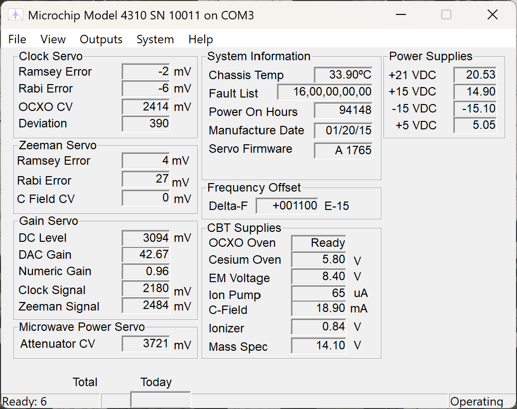
The atomic clock has been resynchronized with GPS. The tolerance has been reduced to <1000ns again.
Marc Daniel
We finished the software chanegs for EtherCAT Corner Station Chassis 4.
We found 2 issues related to the power outage:
Baffle PD chassis in EX has a bench suppy that needs to be turned on by hand.
The system is back up and running.
WP 12915
Corner Station Controls Chassis 4 Wiring Diagram - E1101222
EtherCAT Corner Station Chassis 4 - D1101266
Modifications to the Beckhoff chassis - E2000499
The EtherCAT Corner Station Chassis 4 was modified per E2000499. New Beckhoff terminals were installed to support JAC and BHD. A new rear panel was installed to accommodate the new rear adapter boards and shutter control connectors. The din rail power terminal blocks were relocated making the exising power cables too short. New power cables installed to the EtherCAT couplers and power terminals. All field cabling was reconnected, expect for ISC_313. The Beckhoff software will need to be updated.
EtherCAT Corner Station Chassis 4 - Serial Number S1107450
F. Clara, D. Sigg
We switched to the spare slow controls computer that is running Windows 10 IoT Enterprise LTSC, 21H2 (OS build 19044.4780), and the most recent TwinCAT 3.1 (4026.19.0). This TwinCAT version uses a packet manager and has changed the install directory to C:\Program Files (x86)\Beckhoff\TwinCAT. It supports Visual Studio 2022 and the new Altium workflow.
One new "feature" is that the PLC boot project needs to be activated in a separate step (previous versions would do this automatically after a build). We updated the install scripts to accommodate this.
We also tried a new TcIoc that was linked against EPICS 7, but it crashed during SDF restore repeatedly. We reverted back to the previous version linked against 3.15.9.
Jonathan and Yuri
This is a continuation of WP 12886. This is the last physical step in the control room/MSR for the reconfiguration. We ran a fiber from the warehouse patch pannel to h1daqdc0 and replaced the network card with a newer card. We will be renaming h1daqdc0, likely to h1daqkc0 (daqd kafka connector), and converting it to send the IFO data into the LDAS as part of the NGDD project.
Next steps on this work is to work on the software setup, and to install the corresponding fiber patch in the LDAS room.
Jonathan, Dave, Erik, Richard,
As per WP 12886 we reconfigured the DAQD 0 computers. The goal was to combine the functionality of the data concentrator (DC0) and frame writer (FW0) into one machine, consolidating them to one machine. This then frees up the other machine for use with pushing data into the NGDD (Next Generation Data Delivery) kafka brokers in LDAS.
At this point h1daqdc0 is no longer the data concentrator. H1daqfw0 is the data concentrator + frame writer.
This required a few other changes:
Once this work was done and h1daqfw2 was shown to be producing identical frames to h1daqfw[01] work was able to move onto the consolidation.
The basic steps:
the H1:DAQ-DC0 epics variables are used in many places, so Dave and Jonathan configured h1daqfw0 to output H1:DAQ-DC0 epics variables, and put a small IOC together to output the set of H1:DAQ-FW0 variables we need. This is an area we need to revisit. One likely approach is to make use of a feature in cps_recv that outputs the daqd STATUS, CRC_CPS, CRC_SUM variables and then to move the daqd on FW0 back to outputing the FW0 variables.
This work validates that we can combine the DC and FW computers into one.
The next step is to turn the old DC machine into the producer for NGDD data. We will run the fiber to connect it through to LDAS later this week and work on setting that system up.
My checklist for this is in the DCC https://dcc.ligo.org/T2500385
Updated the slowcontrols SDF for h1syscs[aux,isc,tcs]sdf, restarted these processes on h1ecatmon0 and accepted+monitored the new not-init channels.
The update revealed that there are 12 CS AUX channels which are pending to be added to the DAQ (H1EPICS_ECATAUXCS.ini).
+[H1:SYS-MOTION_C_PZTSHUTTER_B_COUNT]
+[H1:SYS-MOTION_C_PZTSHUTTER_B_ERROR_CODE]
+[H1:SYS-MOTION_C_PZTSHUTTER_B_ERROR_FLAG]
+[H1:SYS-MOTION_C_PZTSHUTTER_B_HIGH]
+[H1:SYS-MOTION_C_PZTSHUTTER_B_LIMITS]
+[H1:SYS-MOTION_C_PZTSHUTTER_B_LOW]
+[H1:SYS-MOTION_C_PZTSHUTTER_B_NULL]
+[H1:SYS-MOTION_C_PZTSHUTTER_B_RANGE]
+[H1:SYS-MOTION_C_PZTSHUTTER_B_STATE]
+[H1:SYS-MOTION_C_PZTSHUTTER_B_TRIG]
+[H1:SYS-MOTION_C_PZTSHUTTER_B_VOLTS]