
REMOVE SEARCH FILTER
SEARCH AGAIN
Search criteria
Section: H2
Task: CDS
WP 13069.

"I found two instances of the EPICS IOC running on h0vaclx. I will close them both and start a single new one. I will also check the other Beckhoff vacuum machines and do the same for those if necessary."

I also found two instances running on h0vacmx. Instead of closing both and opening one, I just closed one of the two instances on each of the two computers. Closed WP.
Fil, Ibrahim, Betsy, Oli
Fil conducted grounding loop checks for the BBSS M1, M2, and M3 satamps. Grounding was found for SUS_BS_82 pin 23 and pin 10. After some issues, we managed to replace the grounded QOSEM with a working one, which we later aligned (see Ibrahim's alog 90838). BS M1 F3: was S2600013, now S2600016
SUS_BS_82 is the cable for CH3 (F3) and CH4 (SD), and pins 23 -> 10 are the coils for F3, so there was an issue somewhere between the satamp and F3.
Cables that Fil tested that aren't grounded are:
Testing SUS_BS_82, all pins looked good except for Pins 23 and 10. Below are their readings:
Checking wrt Chamber:
Checking wrt Rack:
Flipping the pos/neg leads and checking wrt Rack:
After we found out that F3 is grounded to the chamber somewhere, we went in and unplugged F3. Once it was unplugged, we tested the cables to see if we were still grounded to determine if it was an issue in the wiring or in the QOSEM. The cables were not grounded, which told us that the issues was with the QOSEM. The installed QOSEM at the time was S2600013. We removed it and installed S2600025, which did not have any grounding issues, but the LED wasn't working on it, so we had to remove it. We then installed S2600016, which was not grounded and was also working fine. Later we centered it in X (90838).
TITLE: 06/30 Day Shift: 1430-2330 UTC (0730-1630 PST), all times posted in UTC
STATE of H1: Planned Engineering
OUTGOING OPERATOR: None
CURRENT ENVIRONMENT:
SEI_ENV state: MAINTENANCE
Wind: 13mph Gusts, 7mph 3min avg
Primary useism: 0.01 μm/s
Secondary useism: 0.12 μm/s
QUICK SUMMARY:
Ops workstation (cdsws29) was stuck recovering from morning reboot (hit the on/off button to restore). nuc23 & nuc22 look like they partially came back (will need to log back into them to sort their app windows.
BSC2 SEI work continues (w/ L4C swap & other final checks), FARO measurements may be complete (but FARO remains set-up outside HAM3 just in case). SQZ work continues as well as HAM3 activities and also transfer functions for ITMy.
J. Kissel

This morning, I re-installed the H1SPIH23 pathfinder's photodiode and picomotor cable-table-brackets (CTBs) that had been temporarily moved to upgrade the Corner 1 H1 capacitive position sensor (see LHO:90791), and re-dressed the cabling cable clamps.

As mentioned in passing in LHO:90750 the CRS team will now consume the "spare" SPI_HAM3_004 quadrupus leg, that's J2 of the S2500513 instantiation of D2400342, which manifests as CH8 on the TCSY_C02, Controller 10, PICO G picomotor controller driven by the Corner 2 ECAT chassis -- which shows up on the H1SYSCSAUX computer's SDF system. So this has been routed in the +X direction and up in +Z to the table top on the +Y corner.

I'll post pictures of all the re-dressing in the comments so I can better caption them.
Routing of the J2 leg of the D2400342 picomotor cable to the +Y corner of the table top.


Big picture images of the ST1 portion of the cable dressing on the Corner 1 sensor/actuator hatch.


Zoom of how the 2x D25 cables are routed with a nice soft s-curve as the cables jump from the ST1 suspended stage to ST0 support stage.

Zoom of Cable Table Bracket 1 (CTB-1), which collects
    - (1st Floor) the D25 end of the D2400343 PD concentrator cable SPI_HAM3_[031-034] (hidden from view), and
    - (2nd Floor) the D25 end of the D2400342 quadrupus picomotor cable SPI_HAM3_[001-004]
and sends them into
    - (1st Floor) the ST1 end of 28 AWG D25 cable SPI_HAM3_014
    - (2nd Floor) the ST1 end of 22 AWG D25 cable SPI_HAM3_012

Zoom of Cable Table Bracket 2 (CTB-2), which collects
    - (1st floor) IFO MEAS A/B single-element PDs' duopus
    - (2nd floor) IFO REF A/B single-element PDs' duopus
and sends them into
    - (1st floor) Cable D, i.e. SPI_HAM3_032 of the D2400343 PD concentrator.
    - (2nd floor) Cable E, i.e. SPI_HAM3_031 of the D2400343 PD concentrator.

Zoom of Cable Table Bracket 3 (CTB-3), which collects
    - (1st floor) OL ISIK QPD B
    - (2nd floor) FBR PWR REF/MEAS single-element PDs' duopus
and sends them to
    - (1st floor) Cable B, i.e. SPI_HAM3_034 of D2400343 PD concentrator
    - (2nd floor) Cable C, i.e. SPI_HAM3_033 of D2400343 PD concentrator

h1susbs is now fully running the BBSS and everything that was previously on the h1suslo12 model was moved over. The channels that were previously called SUS-BBSS are now called SUS-BS. Old SUS-BBSS data can still be grabbed by using nds2.
I unpaused the BS guardian and took the suspension to DAMPED. It is damping.
/opt/rtcds/userapps/release/cds/h1/medm/SITEMAP.adl
r35324
- Removed BBSS(temp) and updated link for BS
/opt/rtcds/userapps/release/sus/h1/medm/susbs_overview_macro.txt
r35325
- Copied over susbbss_over_macro.txt and updated optic name and dcuids
/opt/rtcds/userapps/release/sus/common/medm/bbss/SUS_CUST_BBSS_QOSEM_OVERVIEW.adl
/opt/rtcds/userapps/release/sus/common/medm/bbss/SUS_CUST_BBSS_M3_OPLEV.adl
r35327
- Removed temporary 'lo12' filled in optic names and replaced with $(optic)
/opt/rtcds/userapps/release/sus/h1/filterfiles/H1SUSLO12.txt
/opt/rtcds/userapps/release/sus/h1/filterfiles/H1SUSBS.txt
r35326
- Copied over previous BBSS filter files into H1SUSBS (with name change from BBSS -> BS)
- Committed updated H1SUSLO12 filter file (which has no filters loaded, which is correct)
/opt/rtcds/userapps/release/sus/h1/burtfiles/h1susbs_down.snap
r35329
- Copied opt/rtcds/lho/h1/target/h1suslo12/h1suslo12epics/burt/safe.snap over to /opt/rtcds/userapps/release/sus/h1/burtfiles/h1susbs_down.snap, which due to symlinks gets linked over to opt/rtcds/lho/h1/target/h1susbs/h1susbsepics/burt/safe.snap
- Loaded BS sdf from safe.snap and 'reverted' changes to get the model to put in the correct settings
TITLE: 06/12 Day Shift: 1430-2330 UTC (0730-1630 PST), all times posted in UTC
STATE of H1: Planned Engineering
OUTGOING OPERATOR: None
CURRENT ENVIRONMENT:
SEI_ENV state: MAINTENANCE
Wind: 13mph Gusts, 9mph 3min avg
Primary useism: 0.03 μm/s
Secondary useism: 0.08 μm/s
QUICK SUMMARY:
It was requested that I try to trend the Oplevs this morning, but the BS SUS screen is full of white boxes that claim their channels don't exit when NDscoped. Tagging CDS.
I did however find the Input Pointing Trends button which gave me the following:
IMs
BSCs (No motion on the BS channels here though which is some SUS-picious BS)
MCs
PRMs


So Dave and I talked a bit about the BS MEDM page VS the BBSS(temp) which Does Indeed have trendable oplevs..... but.... once again there is no motion on those channels either.


I was able to get this H1:SUS-BS_M3_OPLEV data from the last day the NDS2 server.

Erik, Oli
Now that we don't need the BSFM model anymore, we can move the BBSS model over into h1susbs (it was temporarily on h1suslo12). It's been committed to svn as r35313.
I moved the BBSS model from h1suslo12 over to h1susbs. Then I made some more changes to get everything up and running. Both h1susbs and h1suslo12 were successfully able to build on h1build.
Things updated/added/removed:
h1susbs (r35313) - moved what was in h1suslo12 at the time over to h1susbs and then made the following changes:
BBSS_QOSEM_MASTER (r35312):
h1suslo12 (r35318):


J. Kissel

In prep for the eminent install and alignment of the SPI pathfinder, I've added and turned on calibration to convert all PD signals (which come off the ADC as [ADC counts]) into ADC input voltage, like we've been using on the o-scopes in the optics lab.

The "filter," really just a gain is
    Module    Name     Design String     Units
    FM1       cts2V    gain(0.0061035)   [(ADC V) / (ADC ct)]
as the ADC has a 40 [V_pp] (differential) range, spread over 2^16 [ADC ct], hence 40 / 2^16 = 0.00061035156, which I've rounded to 4 significant digits as is typical (see T1100538).

This FM1 module has been copied and loaded into every relevant PD input filter bank, the module is turned ON, and the gain of the bank has been set to +1.0 such that the output of the bank is calibrated. Those calibrated channels (in the order they appear off of the ADC; LHO:89775) are:
    IFO REF A      ::   H1:SPI-H23_IFO_REF_A_DEMOD_SIG_OUT_DQ    ::  2^15 (32768, or "32k")
    IFO REF B      ::   H1:SPI-H23_IFO_REF_B_DEMOD_SIG_OUT_DQ    ::  2^15 (32768, or "32k")
    IFO MEAS A     ::   H1:SPI-H23_IFO_MEAS_A_DEMOD_SIG_OUT_DQ   ::  2^15 (32768, or "32k")
    IFO MEAS B     ::   H1:SPI-H23_IFO_MEAS_B_DEMOD_SIG_OUT_DQ   ::  2^15 (32768, or "32k")

    QPD B SEG 1    ::   H1:SPI-H23_OL_QPD_B_SEG1_OUT_DQ          ::  2^11 (2048, or "2k")
    QPD B SEG 2    ::   H1:SPI-H23_OL_QPD_B_SEG2_OUT_DQ          ::  2^11 (2048, or "2k")
    QPD B SEG 3    ::   H1:SPI-H23_OL_QPD_B_SEG3_OUT_DQ          ::  2^11 (2048, or "2k")
    QPD B SEG 4    ::   H1:SPI-H23_OL_QPD_B_SEG4_OUT_DQ          ::  2^11 (2048, or "2k")

    FBR PWRIN REF  ::   H1:SPI-H23_FBR_PWRIN_REF_OUT_DQ          ::  2^11 (2048, or "2k")
    FBR PWRIN MEAS ::   H1:SPI-H23_MEAS_PWRIN_REF_OUT_DQ         ::  2^11 (2048, or "2k")

    QPD A SEG 1    ::   H1:SPI-H23_OL_QPD_A_SEG1_OUT_DQ          ::  2^11 (2048, or "2k")
    QPD A SEG 2    ::   H1:SPI-H23_OL_QPD_A_SEG1_OUT_DQ          ::  2^11 (2048, or "2k")
    QPD A SEG 3    ::   H1:SPI-H23_OL_QPD_A_SEG1_OUT_DQ          ::  2^11 (2048, or "2k")
    QPD A SEG 4    ::   H1:SPI-H23_OL_QPD_A_SEG1_OUT_DQ          ::  2^11 (2048, or "2k")

I've made ndscope templates for these channels, which live in (hopefully self-explanatory names):
    /opt/rtcds/userapps/release/spi/h1/ndscope/
        FBR_PWRIN.yaml
        IFOs_Raw_Ts.yaml
        QPDA.yaml
        QPDB.yaml

The settings have been saved to the SDF system and committed to the userapps repo under
    /opt/rtcds/userapps/release/spi/h1/burtfiles/
        h1spih23_safe.snap

Also, for the record, Erik just helped me convert the target area .snap files to be softlinks to this one userapps file for now,
    /opt/rtcds/lho/h1/target/h1spih23/h1spih23epics/burt/
        safe.snap -> /opt/rtcds/userapps/release/spi/h1/burtfiles/h1spih23_safe.snap
        OBSERVE.snap -> /opt/rtcds/userapps/release/spi/h1/burtfiles/h1spih23_safe.snap


J. Kissel, F. Clara
WP:13296

%%%%%%%%%%%%%%%
Executive Summary:
Following up after last week's completion of SUS-R2 (LHO:90500), all HAM3 in-air electronics cables and optical fiber patch cords to/from SUS-R2 or TCSY to the chamber have been "pulled," i.e. routed fully to each end of their connections. This leaves *only* the HAM2 ISIJ QPD connection to its transimpedance amplifier in SUS-R1 as the last cable to be landed in the ex-vacuo part of the SPI electronics wiring and optical fiber network.
%%%%%%%%%%%%%%%

Details
Here's the status summary of each of the HAM3 cables and patch cords Fil and I pulled today.

SPI Picomotor Cable SPI_HAM3_013
Description :: This cable connects drive CHs 5, 6, 7, and 8 of the TCSY / CO2Y Picomotor Controller "G" (driven by Corner 2 ECAT Chassis) to the HAM3 D6 12x D25 feedthru into port F11.

Status :: Now connected at controller and at flange. Strain relief at flange is not yet final.

SPI PD Concentrator Cable SPI_HAM3_015
Description :: This cable bus routes the SPI HAM3 ISIK Transceiver PD and QPD signals (IFO_REF_A, IFO_REF_B, IFO_MEAS_A, FBR_PWRIN_REF, FBR_PWRIN_MEAS, IFO_MEAS_B, QPDB_Q1, QPDB_Q2, QPDB_Q3, QPDB_Q4) from HAM3 D6 port F10 to the "PD Input" port of the S2500712 D1002481-v4 "Variant 2" of the SPI transimpedance amplifier (TIA) chassis in SUS-R2 U4.

Status :: Now connected at TIA and at flange. Strain relief at flange is not yet final.

SPI_PSL_001 Optical Fiber Patch Cord
Description :: This optical fiber patch cord connects the fiber collimator SPI-FC1 fiber output of the SPI Pick-off Path in the PSL to the "PSL IN" fiber input port on the front-panel of S2500058 D2400156 SPI Laser Prep Chassis in SUS-R2 U6+U7.

Status :: NOT ENERGIZED (thanks to newly installed Uniblitz Shutter; LHO:90490). BUT -- shielded with standard orange protective tubing and now brought down from the cable tray (2nd story of "high" tray running above the input arm) and landed at the Laser Prep Chassis. Neither strain relief nor routing through rack is final.

SPI_REF_001 and SPI_MEAS_001 Optical Fiber Patch Cords
Description :: This pair of optical fiber patch cords connect the modulated at 80.0 MHz [MEAS] and (80.0 MHz - 4096 Hz) = 79.995904 MHz = "80- MHz" [REF] light from the SUS-R2 U6+7 Laser Prep Chassis fiber output ports to the HAM3 D4-1J1 [S3228003 MEAS] and D4-1J2 [S3228002 REF] fiber feedthrus (D2500175).

Status :: NOT ENERGIZED (no laser input from PSL, nor are the AOMs being driven with any RF). BUT -- shielded with standard orange protective tubing and routed in the "low" cable tray system that runs from SUS-R2 to the feedthrus underneath the -X side of the chamber. They're connected at the SUS-R2 U6+7 Laser Prep Chassis fiber output ports, but they're dangling at the feedthru end because we haven't finished upgrading the feedthrus (see LHO:90511).

References
The SPI Pathfinder has been integrated into lots of different subsystems, so there's a ton of disparate systems drawings that are need to follow its signals from "soup to nuts."

Optical Fiber
[1] D1300348 As-built PSL/IO Table Layout
[2] D2400110 Optical Fiber Routing Diagram

RF electronics and PD Electronics
[3] D2400111 SPI Wiring Diagram
[4] D1002874 HAM3 Flange Layout
[5] G2401479 Systems-level Slides for HAM3D4_12xD25 and HAM3D6_FiberFeedthru plans
[6] SUS-R2 Rack Layout w.r.t. SPI
[7] E1100591 (Heliax) RF Signal Distribution System

Picomotor Drive
[8] E1100892 TCS Wiring Diagram
[9] D1900511 ISC Wiring Diagram
[10] D1100683 EtherCAT (Beckhoff) System Diagram
[11] E1200072 Picomotor Channel Inventory [[Very-out-of-date -- see unresolved IIET:32610]]
Pictures of SPI Picomotor Cable SPI_HAM3_013


Pictures of SPI PD Concentrator Cable SPI_HAM3_015.


Pictures of SPI_PSL_001 Optical Fiber Patch Cord, SPI_REF_001 and SPI_MEAS_001 Optical Fiber Patch Cords


Patrick T., Filiberto C., Richard M., Dave B., Jonathan H., Jim W.

WP 13262.

The summary of the work is detailed in the permit. There were some additional code changes needed to fix a scaling issue and some others made to clean things up. The only thing that should be left is to restart the DAQ to remove three channels.

IOC code:
https://git.ligo.org/cds/software/ads/ads-utils 9b98c481d6f9ab129fa4bc54475e05383d304aa2
https://git.ligo.org/cds/software/ads/epics7-ads c72c97eb4d1558d9de5c03234e90c8c651aab99b (in container), 9e5a10a014beeb0cb7b021649c459a0fa0488be7 (used to generated EPICS db)

PLC code:
https://git.ligo.org/cds/ifo/beckhoff/io 65f59557c1fefc90f4befc9338bd29a1fb27d8e0
https://git.ligo.org/cds/ifo/beckhoff/lho-hepi 3fd31d58fafc08e4d5a84dce1d0d57dfd8b6b74e
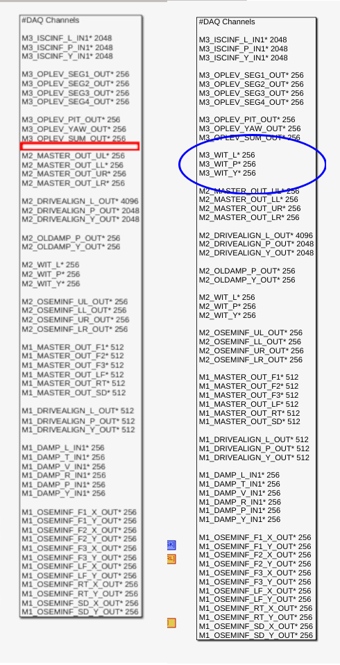
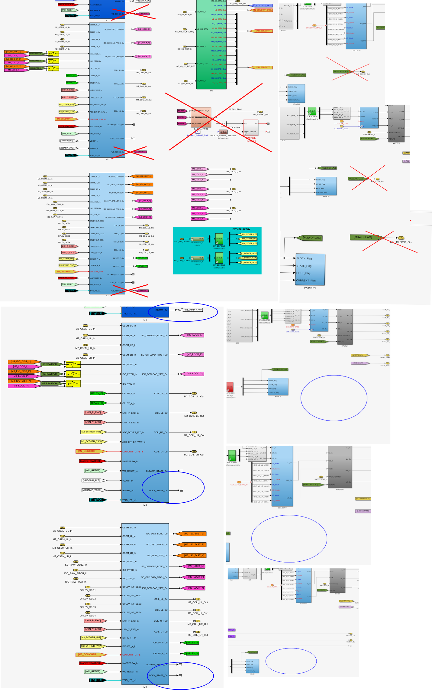
Last Friday, HAM7 was vented and the mega cleanroom was on, but chamber doors were on, FC1 sliders were at 100 urad P, -162 urad Yaw, and the M3 witness sensors were -90 urad pitch, -15 urad. Since then, there was a power outage, the chamber doors are off and the purge air is on, and tha DAC has been changed as it was not working 90454. Now, with the same slider settings (100 urad P, -162 yaw), M3 withness sensors are at 24 urad pitch, -204 urad yaw.
In 89751, Oli noted that turning on the purge air caused a shift of -29urad in the bottom mass osems. If purge air were the only difference between now and Friday, we would expect M3 witness osems to say -120 urad, if the purge air is similar to what it was in December. So, it seems like the electronics change has changed the realtionship between the slider value and the witness sensor.
On May 7th, we moved the pitch alignment slider by 140 urad, and the M3 witness only saw a move of 10 urad. Today, when we move the slider by 262 urad, the M3 witness osems see a shift of 317urad, so the suspension is actuating now, but seems not to have been in May.

Between 7th April and 7th May, and a period around the end of February, the DAC outputs were noisy, before and after this, they are not. I'm not sure what this is, plot attached.
Below is comparing today with Dec 9th 08:30 UTC (when CR was on temp ~71degF, HAM7 vented and doors removed). This shows the sliders are agreeing with what we have seen in the past.
| Temp | Pitch | Yaw | |||
| Slider | M3 WIT | Slider | M3 WIT | ||
| Dec 9th 08:30 UTC | 71degF | 231 | 181* | -153 | -201 |
| Now, June 3rd 21:45 UTC | 71.3degF | 231 | 176 | -153 | -202 |
* drifted down to 162 over next week


Yesterday I made some changes to the h1suslo12 model(before, after). We were now done with the BOSEMs on the BBSS, so we needed the BBSS model to be able to drive to the DAC for M1 so we could test the QOSEMs. We also needed to be able to switch the BIO on the BBSS, so we also needed to connect the BIO senders and receivers back up to be able to communicate with MC2, which controls the BIO switching for the b2h34 models.
To be able to run this updated model, we would also need to stop the h1susbs model so there wouldn't be mulitple sets of channels trying to write to the same DAC.
Erik and Jonathan (90422) helped with stopping h1susbs, and with building and restarting h1suslo12.


Yesterday (June 1) I replaced a failed power supply on the Comtrol communication device at EY that bridges a dust monitor and a weather station to the network.
Workstations were updated and rebooted. This was an OS packages update. Conda packages were not updated.
J. Kissel"
As is all over the aLOG this morning, LHO had back-to-back site-wide power-outages this past Saturday 2025-05-30 -- LHO:90395. Here's the quick, pain-free record of recovering the SPI pathfinder's function to the levels we left it on Friday 2026-05-29 (LHO:90382).

LASER
State of laser as I found it (entering the lab with laser safety googles ON):
    - Yellow chain and signage across the entry warning of "laser running unattended" still blocking entry.
    - Magnetic lock of "outer" curtain released, manually hook-locked "inner" curtain still closed.
    - Laser hazard sign OFF
    - Laser STOP Button still "OUT" (in the ON position)
    - Laser Hazard sign still keyed "ON"
    - NPRO shuttered, still keyed ON, but not powered.

In short -- everything worked as expected in the event of a power outage if it happened while a laser system was running unattended.

    RECOVERY (all with laser safety glasses ON; obviously but just saying it "out loud"):
    - Unchained and stored "unattended laser" sign.
    - Pushed in ("OFF") laser stop button.
    - Keyed OFF laser hazard sign.
    - Pulled out ("ON") laser stop button to allow for re-energizing of interlock.
    - Keyed ON laser hazard sign.
    - Closed magnetic "outer" curtain and swiped in, laser hazard sign lit up as expected.
    - Confirmed NPRO laser output is shuttered.
    - Looked at NPRO controller, red light ON under the OFF button (as expected because it was already/still keyed ON).
    - Plugged in and turned on PD100D interface for on-board S304C power monitor PD (installed within the laser conditioning/fiber collimating bread-board), confirming 1064 [nm] wavelength readout settings.
    - Waited ~2 minutes for the diodes' controllers to settle, then hit the green ON button
    - No issues with diode temp transients, laser worked just fine.
    - Unshuttered laser, and on-board S304C power monitor PD happily confirmed the expect ~198 [mW].

ELECTRONICS
State of electronics as I found it:
    - Electronics +/-18 V and +/-24.0 V power supplies were ON, with their outputs producing voltage at their nominal settings.
    - Laser prep chassis and PD TIA chassis all showed happy green lights.
    - Keysight 33600A RF source had reset, with outputs off and all the wrong settings.

    RECOVERY (all with laser safety glasses ON; obviously but just saying it "out loud"):
    - Ran through T2600039 to restore all frequency settings
    - Exported March 2026 notes to LHO:90409 and restored CH1 (REF) and CH2 (MEAS) amplitude settings to -1.7 and -1.4 [dBm], respectively
    - Turned CH1 and CH2 output ON.

    Laser Prep Chassis SM05PD01A monitor PD ADC voltage: 7.83 [V].
    Laser Prep Chassis RF monitors M2 (REF) and M3 (MEAS) ADC voltage: ~750 and ~750 [mV]
    FBR_PWRIN_REF On-board power monitor PD ADC voltage: 4.68 [V].
    In short :: All these monitor ADC voltages are at normal values.

SPI IFOs
    No actions required after turning on LASER and ELECTRONICS.
    REF IFO Efficiency -- 4.96 V / (2 * 2.69V) = 0.922
    MEAS IFO Efficiency -- 3.00 V / (2*3.95 V) = 0.38

Recovered!
Hopping back into The Mystery Machine...
J. Kissel, J. Warner
ECR: E2400026
WPs: 13237, LHO:13238
Final Design Doc: T2400145
Relevant Systems Level Drawings:
    . Mechanical Assemblies
        :: ISIJ Reflector D2400102
        :: HAM Table Baffles D1700335
        :: HAM2 Systems Layout D0901083 (not yet-inclusive-of-SPI)
    . Electronics Wiring Diagram
    . Cable Routing In-vac Cable Routing Plan from G2401479 (pages )
    . Flange Layout D1002873-v11

Executive summary:
    - Removed ISIJ +X-side, center, HAM2 ISI table baffle from D1700265-v4 Type 2
        :: Bracket mounting bolts left screwed into ISI optical table for this will eventually become a D1700265-v4 Type 3 and remounted.
    - Installed ISIJ Reflector + QPD Assembly D2400102 on +X ISI side wall (D071057-v2), with its shroud (D2500030) in place
        :: We didn't weigh it, but the SW Assembly predicts a mass of 1.96 [kg], which we can likely round up to 2.0 [kg] with the shroud installed.
    - Routed and connected QPD read-out cable system to D3 flange, F10 spigot.
    - Routed and connected picomotor cable system to existing D1101515 quadrupus leg Cable #3, J4
        :: Cable #4, J5 is connected to IO PM5 mirror, Cables #2 J3 and #1 J2 were reset in neat coil with connectors floating to avoid electrical grounding as before.
    - Nudged make-shift baffle system using D1700261 ballast mass baffle mounted vertically on the +X / +Y / Beam Height corner of the chamber wall upon entry into beamtube.
        :: the will DEFINITELY need a technically-minded reset.

In at 10:30a PT and out by 12:30a PT. It's so lovely when everything goes to plan!

Pictures and further info to follow in the comments below.


Removing Center ISI Table Baffle

Not much to say more here -- removal was easy. We tried "just" removing the panel using the the coated/capped screws, but these didn't budget upon several attempts with Jim's fingers and grunts. So, elected to fight that battle outside the chamber and removed the whole assembly at the table mounting point.

The full assembly is wrapped in dry-wipes, foil, and ameristat bagged and in Mitch's office while it waits for the Type 03 version of the panel to come out of clean-n-bake.


Installation of ISIJ Reflector itself

Also not much to say, other than the great joy that the drawings of the D071057-v2 ISI Side Wall have the irregular positions of the 1/4-20 utility holes accurate enough that Bram's CAD-informed-only mounting holes for the ISIJ reflector's baseplate of the reflector lined up without issue. *phew*

Also -- the D2400102 drawing doesn't highlight which length 1/4-20 bolt should be used for mounting, so we used 1/4"-20 x 0.625"L (5/8"), which was "just enough."

Pictures from the main entry are the best "big picture" views, but here I attach a few more in case the need arises.


QPD Cable Routing

We didn't get dedicated pictures of this QPD cable routing but,
    - it follows the plan on page 22 of In-vac Cable Routing Plan posted to G2401479-v3,
    - You can see the ST1 portion of it well-enough in the above pictures,
    - Jim did the routing, so I trust that there's a healthy loop in the jump from ST1 to ST0, and
    - I attach a picture here of the record that we've connected it to D3-F10, and a copy of the "F-Type" (D2000225-v1) counting from page 18 of the above mentioned cable routing plan.


Picomotor Cable Routing BEFORE INSTALL

Just because we knew little about the details of this cable system ahead of time given how ancient the PM5 picomotor actuated mirror system, I got a lot of good "before" pictures. Mostly, I confirm that PM5 does use the Cable #4 J5 leg of the D1101515 quadrupus, and all the other legs were neatly cable-tied up and away.


Picomotor Cable Routing AFTER INSTALL

Here're photos of the routing of the two 72 [in] length D2400316 picomotor extension cables connected in series and routed to all the way around from the ISIJ reflector on the +X face to the -X / +Y corner of the table where CB-9 and the D1101515 quadrupus lives.

I paid particular attention to the connectors and made sure they were left floating and not shorting to anything metal.

I also re-bundled up Cable #2 J3 and Cable #1 J2 in coil similar to the before pictures, again ensuring that the connectors are floating in both space and electrical connection.


The Nudged Chamber Wall Baffle

Some pictures of the baffle that we nudged that will likely need re-alignment.


tagging for photos.
On the new channel assignment of HAM2's SPI ISIJ picomotor, and why I'm confident it's CH7:

Per D1000581-v13, page 13 and then D1900511-v12 page 17, I'm quite confident that the quadrupus cable and up in CH5-8 of the controller on IOT2L, called "PICOMOTOR 5" in D1900511, which I guess becomes "Picomotor B / Slot 2" on page 2 of the ECAT System Diagram D1100683-v11.

This is corroborated with opening up the picomotor MEDM screen -- sitemap > LSC > picomotors > "HAM 2 + oplev" button (that has "controller 5" and "PICO B" next to it), and clicking through the channels and seeing that CH8 is called "PSL ISS QPD/PD (PM5)."

Here's a labeled picture that makes things more clear.

Belated aLOG on in-vac cable routing of the ISIJ QPD A PD and serial number assignments:

Path       PD Name    PD SN          Monopus            D9-to-D25 Monopus
                      |----------D2600002--------|
                      D1600083 Type 3     D2400340      D2300128
OL ISIJ    QPD A      S2401092            S2500517      S2500511

Workstations were updated and rebooted. This was an OS packages update. Conda packages were not updated.
J. Kissel, T. Roocke

I was crossing the t's and dotting the i's on our documentation to better understand what calibration / compensation to install into the new SPI front-end / MEDM infrastructure.

As such I was reconciling / validating the calibration info that Sina put in LHO:89739 (originally informed by derivations in E2600104) against the info Tom put in the three travelers
    - S2500711 (Variant 1 for the HAM2 YAG444s),
    - S2500712 (Variant 2 for the HAM3 4x FFD200s and one YAG444), and
    - S2500713 (Variant 3 for the HAM3 additional 2x FFD200s)

Two things were amiss:
(1) The values of resistors and capacitors were not consistent between Sina's "R4 Resistor value now (kohm)" and "C5 capacitor value now (pF)" columns, and what Tom stated in the traveler update. As such, I asked Tom to give me more detailed confirmation -- and he delivered excellently:
    S2500711 (Variant 1 for the HAM2 YAG444s)
    CH1-4
        . R4 = 1.54kohm (P1.54KFCT-ND)
        . C4 = 2.2nF (399-8171-1-ND)

    S2500712 (Variant 2 for the HAM3 4x FFD200s and one YAG444)
    CH1-2
        . R4 = 4.99kohm (P4.99KFCT-ND)
        . C4 = 560pF (PCC561BCT-ND)
    CH3-8
        . R4 = 3.32kohm (P3.32KFCT-ND)
        . C4 = 1nF (PCC102BCT-ND)

    S2500713 (Variant 3 for the HAM3 additional 2x FFD200s)
    CH1-2
        . R4 = 53.6kohm (P53.6KFCT-ND)
        . C4 = 220pF (478-1484-1-ND)

(2) In our testing of the TIAs both *before* and *after* these component values were installed, we were comparing values measured power values with a Thorlabs S121C power meter (in [mW]) against the TIA ADC output voltage on the positive leg *only* (in [V]), after having verified that the negative leg consistently reported the negative of the positive leg on all channels.

In E2600104-v1 the AA column for "PD Calibration" -- and thus Sina's "PD calibration (mW/V)" column in LHO:89739 is the ratio of the power and positive leg only, and thus missing a factor of 2.0.

So ... there's the updated table, with
    - the transimpedance gain, "TIA gain" calculated as R4 * 2 [V_SE/V_DIFF], with the factor of two from the last ADC driver stage
    - when engaged (rather than bypassed), the whitening stage with
           z1 = 1 / ( 2*pi* (R1*C1 + R3*C2 + R3*C1) )
           z2 = (R1*C1 + R3*C2 + R3*C1) / ( 2*pi* (R1*C1*R3*C2) )
           p1 = 1 / ( 2*pi* (R1*C1) )
           p2 = 1 / ( 2*pi* (R3*C2))
    - FBR_PWRIN single-element PD Calibration at DC
            (power at PD) / ( 2 * (ADC volts pos leg) )
    - IFO single-element PD calibration at DC
            (SIG power + LO power) / ( 2 * (SIG ADC volts pos leg + LO ADC volts pos leg) )
    - QPD segment calibration
            percentage of voltage = ADC volts pos leg of each segment / (total pos leg voltage on all segments)
            (total power at QPD * percentage of voltage) / ( 2 * (ADC volts pos leg of each segment) )
    - a 16 bit ADC with 40 Vpp DIFFERENTIAL range, i.e. 40 / 2^16 = 6.1035e-4 [V/ct] or 2^16 / 40 = 1638.4 [ct/V] (see T1100538)


    DIGITAL NAME     ANALOG    R4        C4       TIA Gain   PD/SEG Calibration   TIA HF Pole    Whitening
                     NAME      [kOhm]    [nF]     [V/A]      [mW/V]               [kHz]          (z1,z2:p1,p2) [Hz]
QPDA
    OL_QPD_A_SEG1    CH1       1.54      2.20     3.08e3     2.0556               46.976         (0.394, 8.06e6: 39.8, 79.6e3)
    OL_QPD_A_SEG2    CH2       1.54      2.20     3.08e3     2.0556               46.976         (0.394, 8.06e6: 39.8, 79.6e3)
    OL_QPD_A_SEG3    CH3       1.54      2.20     3.08e3     2.0556               46.976         (0.394, 8.06e6: 39.8, 79.6e3)
    OL_QPD_A_SEG4    CH4       1.54      2.20     3.08e3     2.0556               46.976         (0.394, 8.06e6: 39.8, 79.6e3)


IFO
    IFO_MEAS_A       CH1       4.99      0.56     9.98e3     1.0959               56.955         bypassed
    IFO_MEAS_B       CH2       4.99      0.56     9.98e3     1.0619               56.955         bypassed
    IFO_REF_A        CH3       3.32      1.00     6.64e3     0.6042               47.938         bypassed
    IFO_REF_B        CH4       3.32      1.00     6.64e3     0.6304               47.938         bypassed

QPDB
    OL_QPD_B_SEG1    CH5       3.32      1.00     6.64e3     0.3667               47.938         (0.394, 8.06e6: 39.8, 79.6e3)
    OL_QPD_B_SEG2    CH6       3.32      1.00     6.64e3     0.3667               47.938         (0.394, 8.06e6: 39.8, 79.6e3)
    OL_QPD_B_SEG3    CH7       3.32      1.00     6.64e3     0.3667               47.938         (0.394, 8.06e6: 39.8, 79.6e3)
    OL_QPD_B_SEG4    CH8       3.32      1.00     6.64e3     0.3667               47.938         (0.394, 8.06e6: 39.8, 79.6e3)

POWER
    FBR_PWRIN_MEAS   CH1      53.60      0.22   107.2e3      0.1154               13.497         bypassed
    FBR_PWRIN_REF    CH2      53.60      0.22   107.2e3      0.1176               13.497         bypassed


I've updated E2600104 (the google sheet), exported it and uploaded that to -v2 to corroborate.
J. Kissel, S. Koehlenbeck

Executive Summary: as an initial guess -- we chose DEMOD parameters as follows:
    . SIG Bank = NO pre-demodulation filtering (just frequency-independent calibration)
    . I & Q Banks = a comb of notch filters at 4096 Hz (the 1f DEMOD frequency), and 8192 Hz (the 2f DEMOD frequency) and a super simple single-pole 200 Hz low-pass.
as the DEMOD filters for the demodulation of signals from the SPI pathfinder's IFO PDs.

I now have a user interface (LHO:90006) to the SPI pathfinder front-end model infrastructure (LHO:89777), so we're now thinking about filling in that infrastructure with real science (or at least real digital signal processing).

SIG filters
One of the core principles of the SPI pathfinder's longitudinal degree of freedom is demodulating the 4096 Hz between note between the MEAS and REF beam. We only expect to use the SPI up to ~10-50 Hz, as the demodulated interferometer PDs noise floor begin to be limited by ADC noise ~5 Hz -- see LHO:83412 and detailed noise budget in Figure 1bii.1 in T2400145. Of course, it remains to be seen how much displacement signal we see above this noise floor.

Traditionally when demodulating nowadays, we're looking for the amplitude and phase of the excitation line we inject among surrounding noise that we don't want (think ADS lines, calibration lines, violin mode and PI damping, etc). In that case it makes sense to band-pass the raw signal pre-demodulation -- this is why you see narrow band-passes in many SIG banks. However, in the case of the SPI IFOs and other heterodyne IFOs, we're actually quite interested in the "noise" -- the "excitation line" is instead the carrier frequency, and the "noise" is the phase signal that we then interpret as differential displacement. As such, the design of the SIG, I and Q filters has an entirely different mentality:
    - in the "find the amplitude and phase" mentality, you want a tight band pass on the excitation frequency in the SIG bank, and then as low-a-frequency low-pass filter that you're patience allows.
    - in the "measure the sideband noise out to 100 Hz or so" mentality, you want as little filtering magnitude / phase distortion as possible from any filtering while sill removing any noise above the band of interest from the signal, post demodulation -- which is typically down-conversion from the 2f signal.

So -- we want *no* filtering in the SIG bank prior to demodulation, and a low-pass that has minimal in-band magnitude ripple and minimal in-band phase loss.

Attached is a trade study of filters that show the magnitude, phase, and step response for several options. All these options are installed in the MEAS A and B and REF A and B I and Q filters, but we've turned only the comb and single pole.


FOM notes: