corey.gray@LIGO.ORG - posted 11:24, Wednesday 04 August 2010 - last comment - 11:30, Wednesday 04 August 2010(119)
HAM-ISI Unit#2: Testing Begins, Sensor Feedthroughs, Sensor Target Surface Contacted
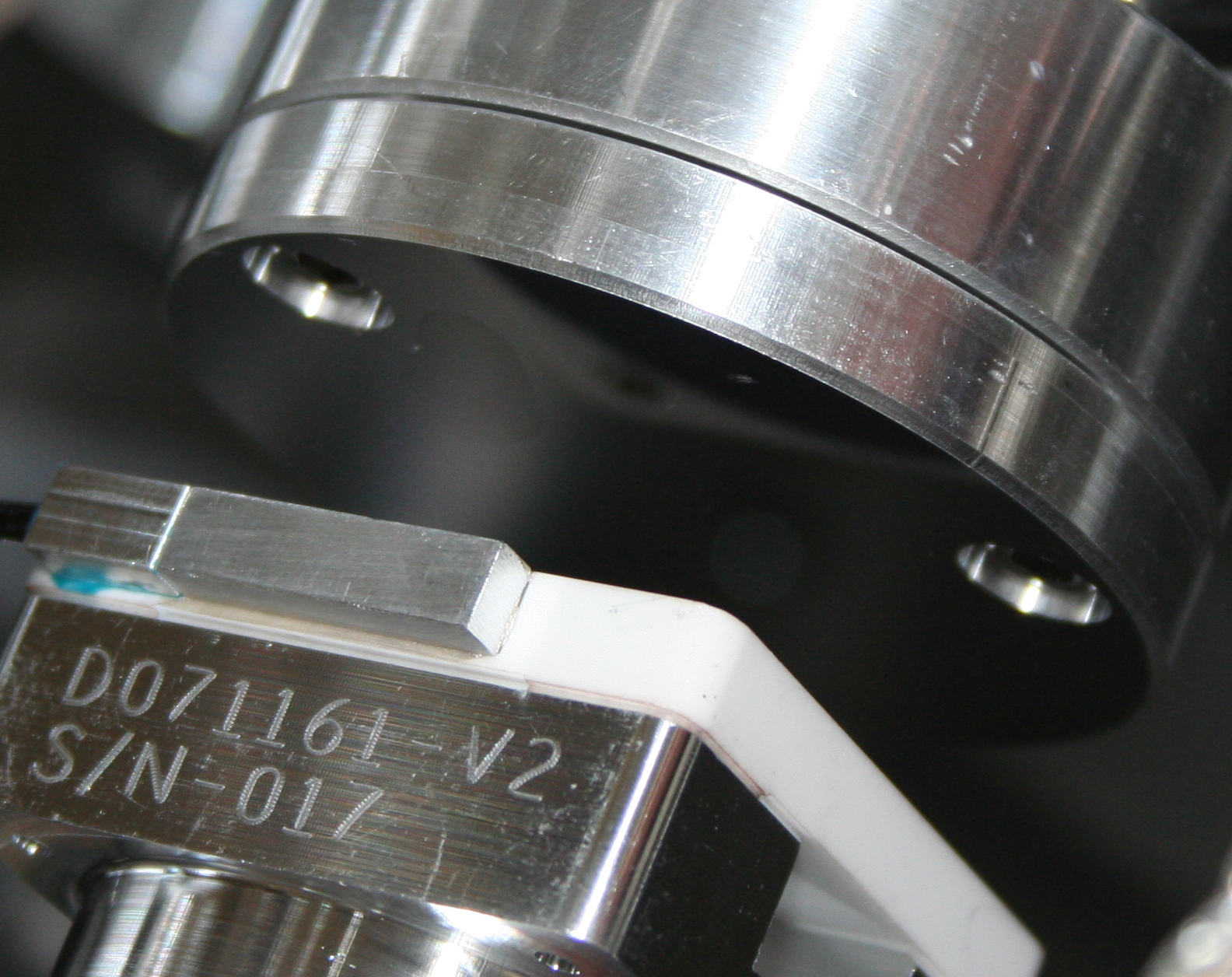
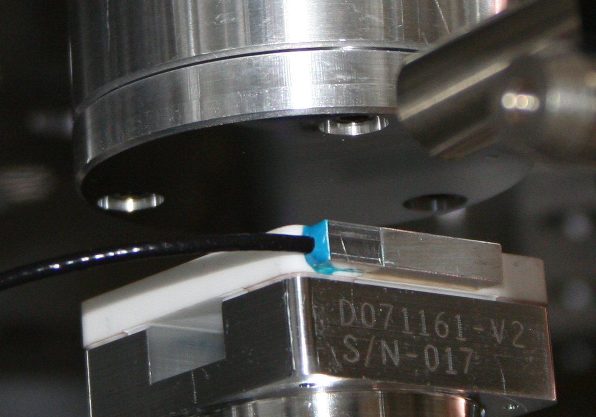
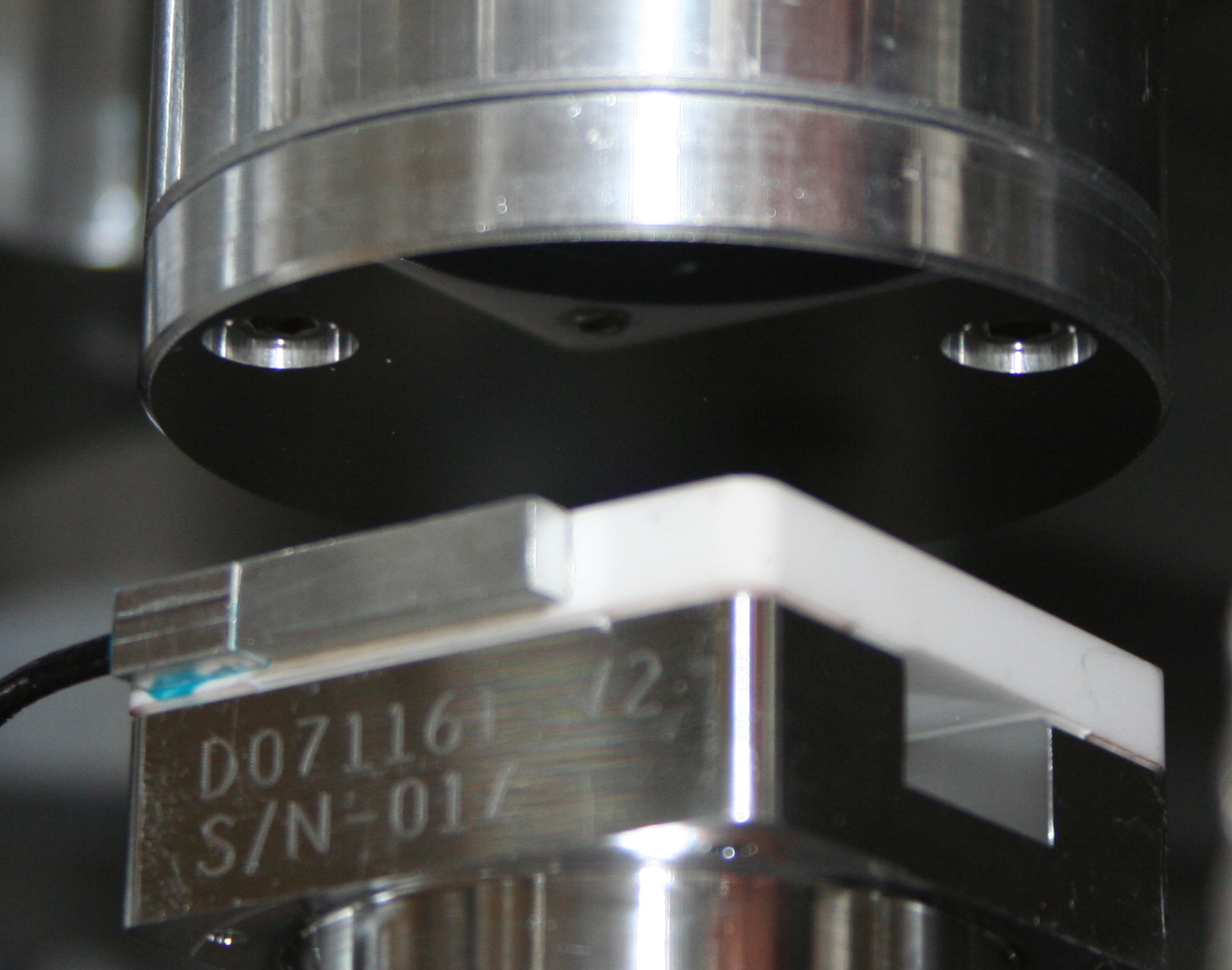
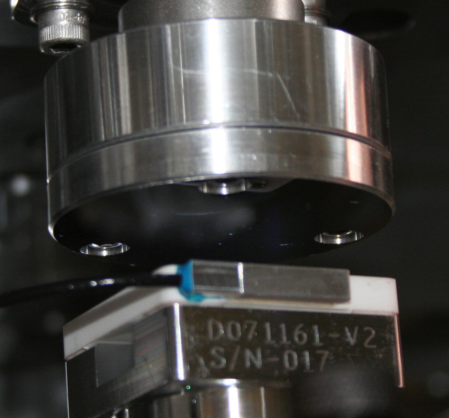
(Corey, Jim, Mitch)

Vertical Sensors Installed On Unit #2
On Unit#1, it was discovered the mirrored surfaces for one of the Capacitive Displacement Sensors (CPSs) was scratched.  We grabbed spare hardware to be used for Unit#2 to get us through Unit#1.   Unfortunately, the Sensor Target Body is the one part we didn't have a spare of.  Hoped to have another one in hand late last week, but as of Tuesday we still hadn't received it, so we opted to use the damaged (yet serviceable) Target body so we could get Unit#2 available for testing.  All Vertical Sensors were installed.  The bad target body is on V1:  we'll want to swap it out when we get another Target Body part.

Pair of CPS Mini-Racks Powered ON (& Connected Together), and Gaps Set

Mini racks were connected to each other with the cable/connections & were both powered on.  Since all the CPS Targets were pulled back (huge gap), we saw that V1,H1,V2, & H2 were railed at +32k.  V3 & H3 were at zero (we saw this on Unit#1); they went to "real" values when the Target was close enough to the Sensor Head.

With the table locked, the Sensor gaps were set to under +/- 100 counts.  Note:  These values can change up to a few 100 counts due to the ~2" slop in the locked Lockers, so don't spend too much time getting gaps right at zero.

Not posting gap values here, because of what was discovered later....

Access Walls Installed, and Unit#2 Balanced & Level Checked
After the Access Walls were installed the Dial Indicators were set to zero (with locked table).  The table was then unlocked and the table was balanced.  The table had already been set fairly close to level weeks ago, so only small moves were needed.  The level of the table, as told by the Dial Indicators was:

A:  0.000"
B:  +0.0005" (this means it's low)
C:  0.000"
D:  0.000"

Pretty darn good!!

Checking Sensor Gaps With Teflon Shims
From the first gap check, it was clear our gaps were big.  Here's what we had:  (all +/- 0.003")

V1:  0.096"
H1:  0.094"
V2:  0.096"
H2:  0.094"
V3:  0.100"
H3:  0.090"

QUESTION:  (1)Switch back to the "real" feedthroughs" or (2) set gaps to 0.080" and set new zeroes on mini-racks??

Flange Feedthroughs Used & Gaps Set Again
I had thought we had installed some new & better BNC feedthroughs on our Interface Plate, but maybe something happened to them after they were cleaned.  Since I found the "real" flange feedthroughs, I opted to employ them again.

[I wired them up such that, when looking at the "dirty side", the top connection is V1, and then incremented up clockwise--same for the H's as well]

Sure enough, with these new feedthroughs, all the counts went up to around 10,000 (meaning the gaps needed to get smaller.  Here are the new values:

Gaps (counts) set with a locked table:  (Offset / Std Dev)

V1:  46  /  1.5
H1:  21 /  0.7
V2:  -55 /  1.5
H2:  -36  /  0.8
V3:  43  /  1.5
H3:  -76  /  0.7

Gaps Measured with teflon shims (all +/- 0.003")

V1:  0.082"
H1:  0.083"
V2:  0.082"
H2:  0.083"
V3:  0.077"
H3:  0.083"

How does this sound?  Are we sure it's a feedthrough issue?  Are we happy where the zeroes are set on the Mini-Racks?

V3 Target Contacted Sensor Head
While finishing up setting the V3 gap, I accidentally loosened the Collar too much and the Target dropped down on to the Sensor Head.  It was a straight drop.  There was no rotation, and I immediately pulled it all the way up, and inspected the Target as best as I could.  I could see a few minor scratches, but they mainly looked like they were on the outer edge.  There were some particles also observed.  The biggest feature was a "dried liquid stain" sort of near the middle.  Since there wasn't anything huge in the middle, I opted to continue with setting the gap.

I took some pictures, so please check them out.  Any suggestions on whether it's ok to live with this situation?  Otherwise, I say we should just proceed and just remember that this happened (in case this Sensor gives questionable performance in the future).

Speaking of things to remember, we also have to remember to swap out the V1 Sensor Target at some point for a good Sensor Target Body (we should get one from LLO on Wed afternoon).

Attached are some close-up photos of the V3 Sensor Target.  In some of them you will notice the "dried liquid spot" which is fingerprint size and near one of the bolt heads.
Images attached to this report


Comments related to this report
More On BNC Feedthrough Situation
Just got off phone with Hugh, and he mentioned the BNC feedthrough on the Interface Plate were never swapped out.  So we don't have the good ones in there.  We'll probably stick with the Flange feedthroughs for now, but we might test out the new BNC feedthroughs at the end of Unit#2 Testing (or just wait until we're on Unit#3).

More On Vertical Sensors
Talked to Hugh this morning about what happened with V3, and sounds like Hugh will give this Target an inspection and determine whether it needs to be swapped out (and if they get the new Sensor Target Body for V1, they might address it, too).