Betsy, Sheila, Keita, Arnaud, Thomas
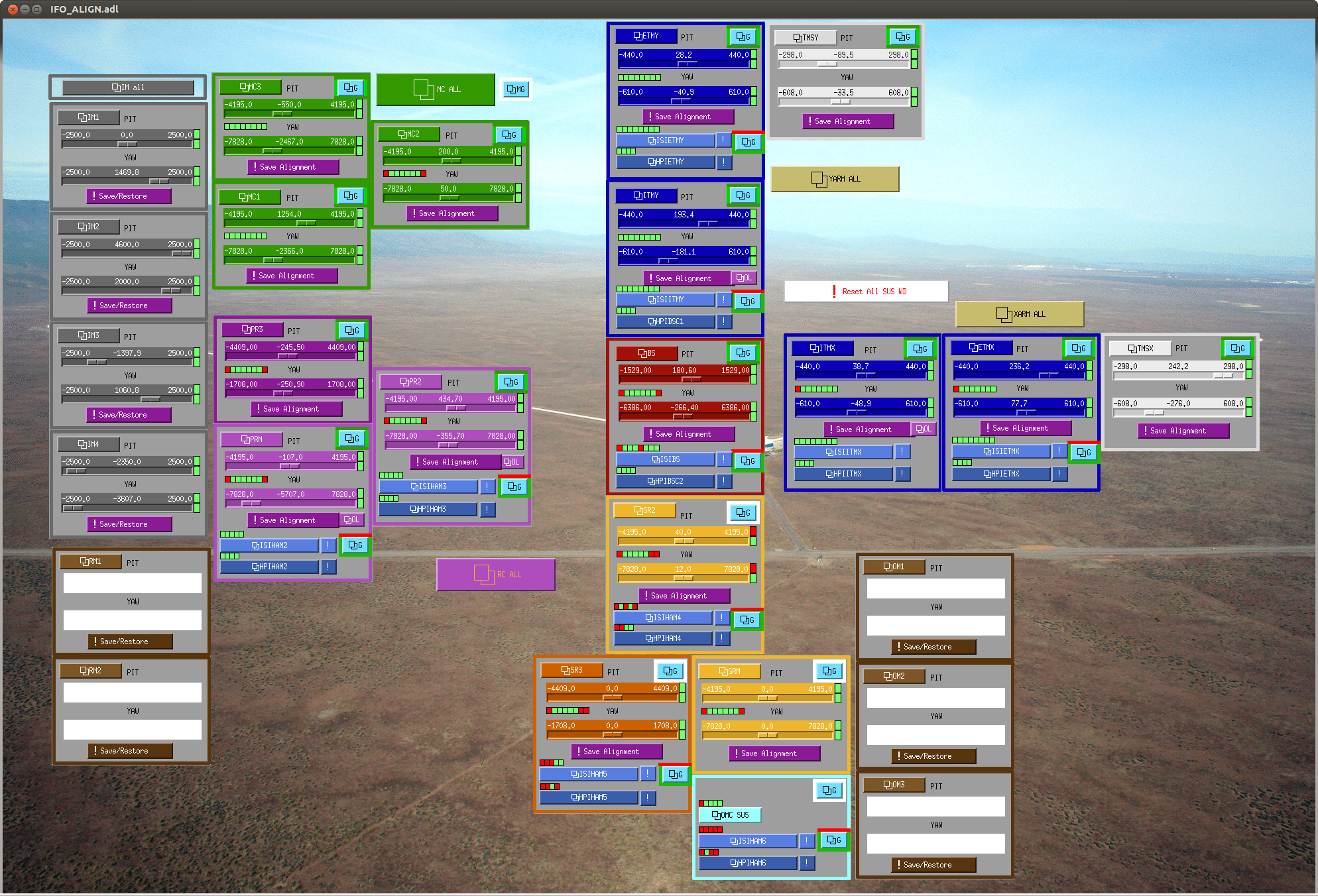
Here is a snap shots of the current alingment offsets. This alingment was checked quickly this morning, both of the arms are flashing green so the ITMs are within a urad or so of alinged.
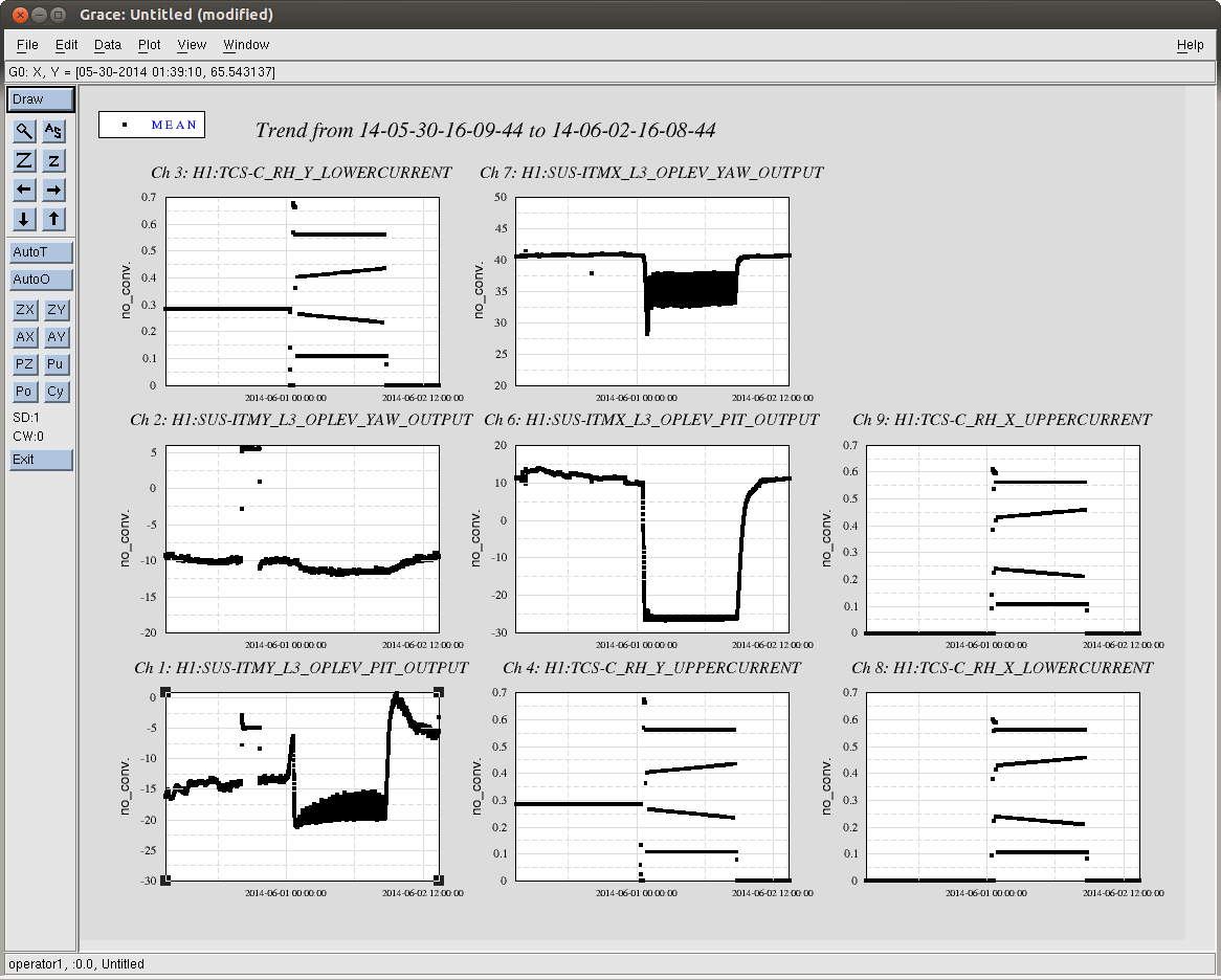
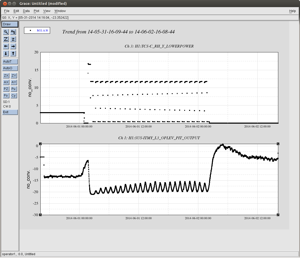
We noticed that the ailngment of ITMY was off by about 8 urad in pitch from the saved offset, this seems to be because turning on and off the ring heater changes the ailngments. Attached are trends of the OpLevs durring the ring heater stress test this weekend, the itms moved by 2-5 urad in yaw, and both moved by about 30 urad in pitch. The third screenshot shows how the pitch changed as the ring heater power cycled.
@DetChar -- can you grab calibrated ASDs of the optical levers before and after the ring heaters are on full blast? It looks like they not only displace the optic in angle, but also add noise. It would be good to quantify this early, so we can fix it!
I forgot to check this.

https://dcc.ligo.org/LIGO-T1100184
Phil Willems wrote a document (T1100184) that predicted around 0.9urad of pitch per Watt of RH power. We applied 27W of power, so the Spurious Willems Pitch is around 24urad. This seems consistent with what was seen. It's worth a more detailed look though.

I can't explain the 8urad offset between the start and finish.
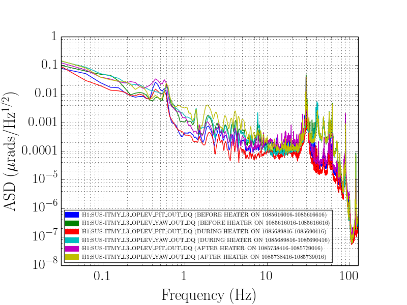
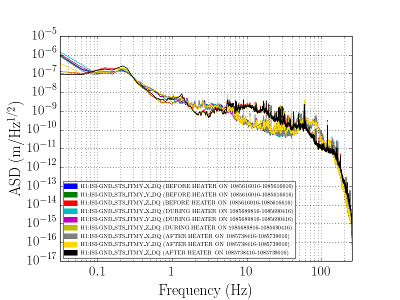
From Jeff's request I've taken a look at the Oplevs before, during and after the heaters were on and found their ASDs (1st plot). These ADSs are taken over 10 minutes and the times are noted in the legend. I specifically chose times where the ITMY ISI ODC is reporting a good state. In addition the BLRMs look normal and similar for all three times. I also found the ground motion ASDs for these times (2nd plot) to reconfirm the ground motion is similar for all three times.

Conclusion - the ASDs for the Oplevs look very similar before, during and after the heaters are on; they don't appear to add extra noise. There is perhaps an extra peak between 7-8Hz in the YAW when the heaters are on but other than that nothing stands out.
There is also a DC power level difference between states before after the weekend stress test. Based on the channel H1:TCS-C_RH_Y_LOWERCURRENT and Aidan's note of 27 W in the ramp up state, the forementioned DC offset correspond to a power level difference of ~8 W (assuming 0.55 for the current level during stress test and 0.3 before the stress test and 0 after the stress test, obtained from the plot of H1:TCS-C_RH_Y_LOWERCURRENT; 27 * 0.3^2/0.55^2). From the dcc documnet noted in the Aidan's comment this correspond to ~8 urd difference we between the initial and end states. This also means that we probably have to make new reference with the current setting (of zero current), if desired.
The ITMY ring heater was set to 8W during the past commissioning period to correct for the fact that we had an ETM with ITM coating installed. This will be changed in the current installation phase. New references will be rquired when we have the new optics installed and aligned.
Also note, the ITMs that this ring heater test was performed on are hung from metal wires in stead of glass fibers. I wonder if this is what is making them more susceptible to steering errors when the ring heater is engaged... The current install is to swap these ITMs out for new units complete with glass fibers. Hopefully the ITMs won't be as susceptible to mispointing when on fibers if this is the case.
J. Kissel

As Betsy indicates these ITMs are suspended via steel wire instead of fused silica fiber. This plays a difference in the compliance used in the Phil's calculation of the expected displacement in T1100184.

Also, the Willems calculation uses a QUAD suspension model from T1000263 which is an out-dated model parameter set that was never confirmed against real measurements (which we now have).  Also it's unclear which Stage / DOF to Stage / DOF was used to produce the "pitch coupling" of 0.154 [rad/Nm]. The mathematica notebook that is "available from the author" is regrettably *not* zipped up in the "Other Files" on the DCC card, so I can't confirm. The attached .pdf doesn't have the 0.154 anywhere in the document.

However, assuming the compliance he used was pitch displacement of the test mass from pitch torque on the test mass, the values from the production quad model model (now confirmed against measurement) are
Fiber: 0.141 [rad/N.m] (using the quadopt_fiber.m parameter set)
Wire: 0.105 [rad/N.m] (using the quadopt_wirerehang.m parameter set)
Willems quotes the displacement of the Center of Mass (CoM) as 1.47e-7 [m] for 11 [W] of ring heater power. Assuming the displacement is linear with ring-heater power (safe assumption??), that's
1.34e-8 [rad/W]
The displacement one expects per Watt of Ring heater power from the Willems model of a displaced CoM is then
Fiber:  1.34e-8 [m/W] * 40 [kg] * 9.8 [m/s^2] * 0.141 [rad/N.m] =  7.4064e-07 [rad/W] = 0.74 [urad/W]
Wire:   1.34e-8 [m/W] * 40 [kg] * 9.8 [m/s^2] * 0.105 [rad/N.m] =  5.5154e-07 [rad/W] = 0.55 [urad/W]

And therefore at max power of 27 [W], the ITMs should be displaced by
Wire: 5.5154e-07 [rad/W] * 27 [W] = 1.4892e-05 [rad] = 15 [urad].

This is a factor of two less than what is seen in ITMX Pitch (the cleanest example). For ITMY, I don't think the test mass was allowed to reach equilibrium before the ring heater's power was changed during the power cycling, so it's more difficult to assess the displacement -- but I think it's much closer to 15 [urad] judging by when the test was turned off (presumably it was turned off to zero current, and not the equivalent of 8 [W] that it had been set to as Daniel indicates).
Jeff pointed out that the factor of two in the ring heater deviation could arise from the optical lever gain in ITMY being a factor of two smaller than ITMX. We trust the ITMX's optical lever calibration because its gain was measured using the baffle PDs and the entire 4km arm (noted in ALOG 10331) but it doesn't look like a similar procedure was done for ITMY, or at least we couldn't find an ALOG that indicated as such.