jeffrey.kissel@LIGO.ORG - posted 22:00, Monday 22 August 2011 (1272)
QUAD BIO I/O Simulink/MEDM Upgrade
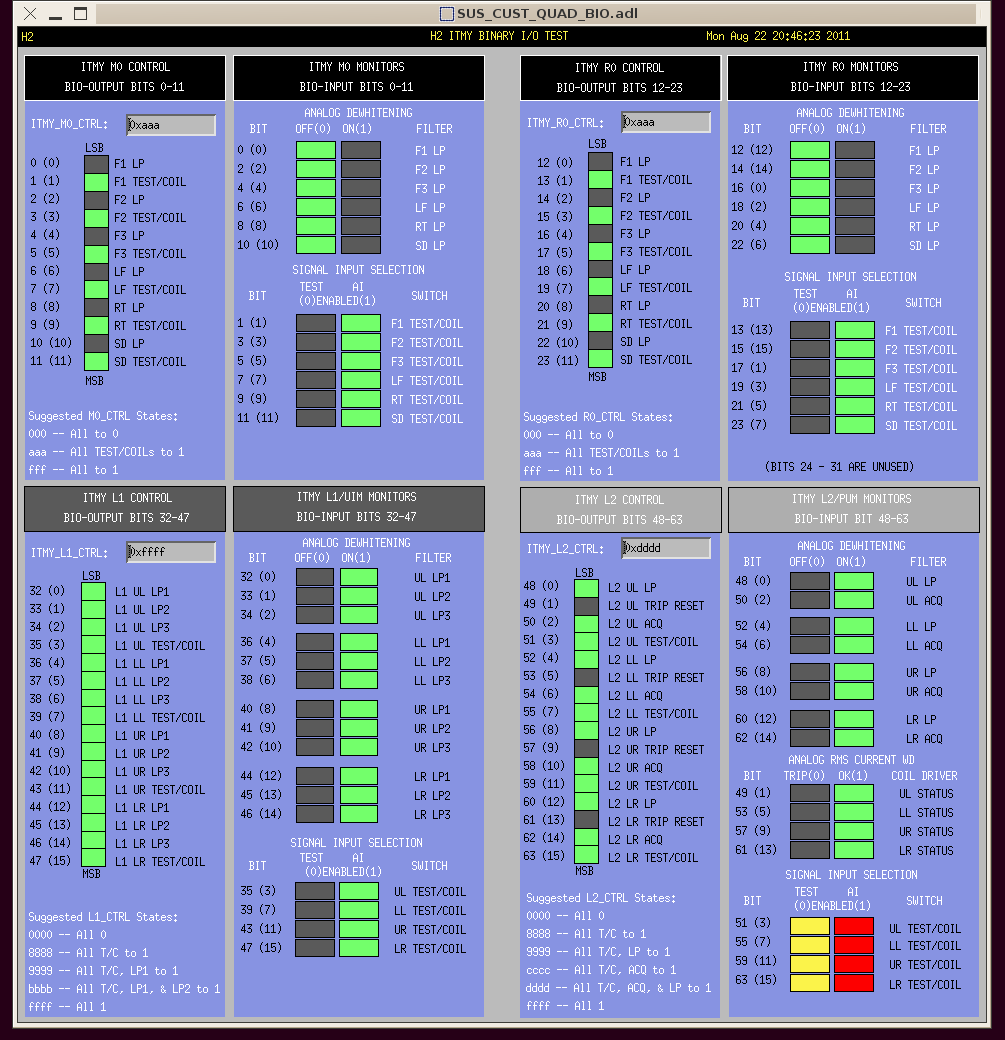
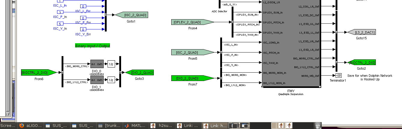
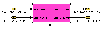
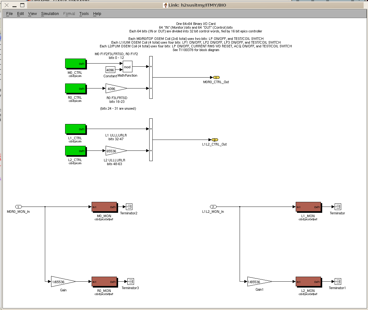
J . Kissel, K. Arai Given that we have a more complete understanding of the QUAD's Binary Input/Output (BIO) switching (arising from conversations with Jay, Filiberto, and Richard, putting it together in T1100378, changing cryptic channel names, and using the monitor chassis), I've reflected the current state of knowledge by giving the BIO simulink block and BIO MEDM screen some TLC. Attached are screenshots of the results. A few interesting points - For every stage, there is a "TEST/COIL" control and corresponding "SIGNAL INPUT SELECTION", TEST or AI monitor bit. Having the control bits set to "TEST" (0) switches the input to the TEST inputs, a separate DB9 connection on the front of the Coil Driver Chassis. Nominally, the output of the Anti-Imaging (AI) Chassis is hooked up to the COIL DB9 inputs. Hence, if you want any drive signal to get from the digital system out to the OSEM COILs, one needs to control the TEST/COIL bits to 1, which corresponds to "AI ENABLED," or a 1 on the monitor bits. - Since have thing control bits set to "TEST" is rarely (if ever) a useful setup, I've colored the monitor bits of the SIGNAL INPUT SELECTION to show YELLOW / RED when the TEST bits are enabled, because it means that no digital drive signal is being received by Coil Drivers. (In the screen capture, the L2/PUM monitors demonstrate this color scheme). - Speaking of the L2/PUM bits, the signal input selection monitor bits are currently busted. The monitor AND ONLY THE MONITOR is stuck in the "TEST" state. Filiberto has discovered that this is because the TEST state corresponds to the "low" (0 V) relay state, and the circuit is still receiving some amount of voltage when switched low, just above the threshold (0.8 V, where the threshold is 0.7 V or something like that). We have confirmed through directly measuring output voltage, and indirectly measuring the outputs via the monitor I/O chassis, that the CTRL bits are working just fine. - Of particular interest to the end users, the suggested states of operation (hexidecimal values entered into:SUS- _ _CTRL) are "hard-coded" written into the MEDM screen - In the simulink model, the EPICs input channels that control the BIO CTRL bits are burried inside the QUAD_MASTER.mdl model, and given cleaner, self-explanatory names repesented on the MEDM screen. And the up-most level of the main diagram (h2susitmy.mdl) design philosophy of having only unique input and output parts on that level has been restored. A few details of the upgrade: The compilation process involved a great deal of excruciating guess and check work. Regrettably, the final design involves lots of notoriously flaky CDS_PARTS, including bus creators/selectors, tags, DIO blocks, bit2word and word2bit parts. In the end, the most painful discoveries were the following: (1) The interaction between what Simulink was designed for and the RCG requires the need for a unit delay *somewhere* in the DIO input / output chain. In reality, the DIO block represents 64 input bits and 64 output bits that are causally disconnected. However, its representation in Simulink appears as though it part of a linear system (like it's a filter bank or something). Hence when the signal chain is connected at the top most level in *what appears to be* a loop, the simulink/RCG compiler freak out when there is no clock-cycle delay between hooking up the output of this "system" to the input. Note that I specify it must be the top level -- I tested moving the unit delay into the subsystem, and it would not compile. This "freak out" is manifested in the compiler as immediately complaining that *all* the buses and tags could not be connected -- which of course lead to a red herring + wild goose chase of slowly implementing baby steps of including buses, then tags, then connecting and reconnecting signals, etc. etc. Moral off the story -- one needs a unit delay somewhere in the DIO signal in the top most level of the chain. (2) Something is terribly buggy with the cdsBit2Word and cdsWord2Bit parts. In the initial design Rolf put together, he had found the need to cdsBit2Word then immediately cdsWord2Bit each of the 4 monitor 16-bit words, before sending them to an epics variable. However, after finally succeeding in surmounting problem (1) I found that *3 of the 4 IDENTICAL connections were functional, but one was not.* Exact same parts, exact same type of input signal, exactly the same style of connection. After peppering the signal chain with test points, I had finally discovered that the cdsBit2Word -> cdsWord2Bit transfer was entirely unnecessary to begin with, so it is now completely removed.
Images attached to this report