alastair.heptonstall@LIGO.ORG - posted 22:11, Wednesday 06 August 2014 (13255)
TCS CO2 Laser Work
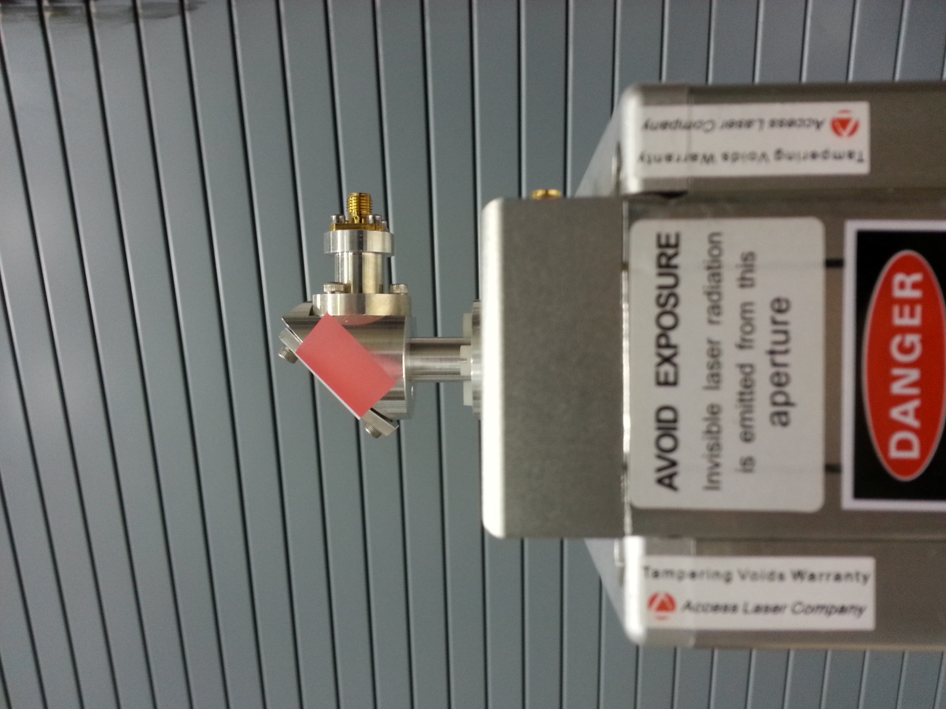
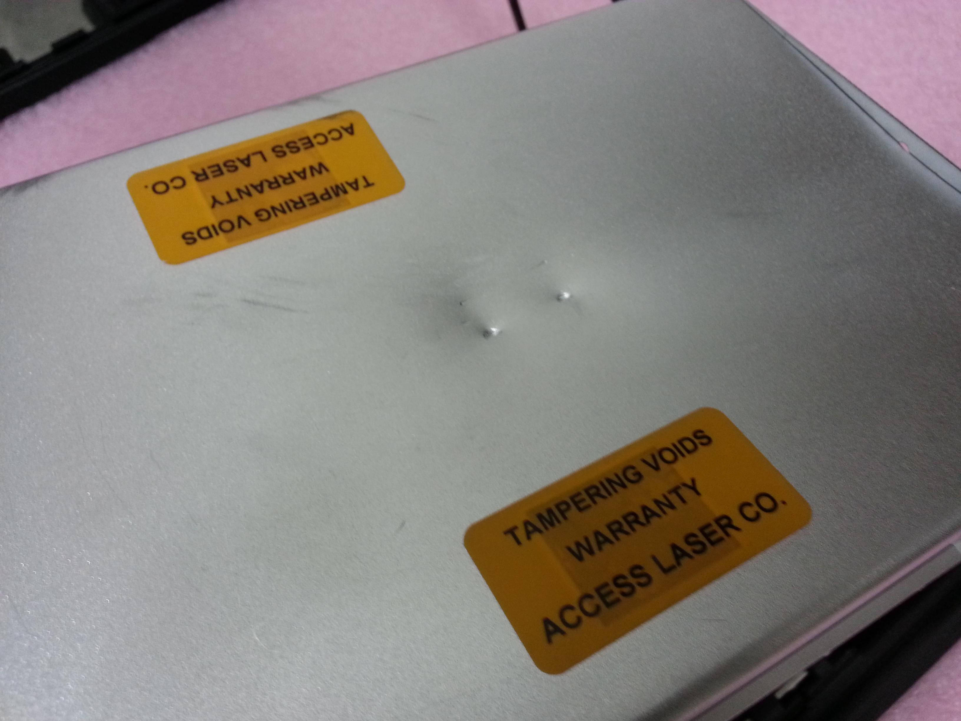
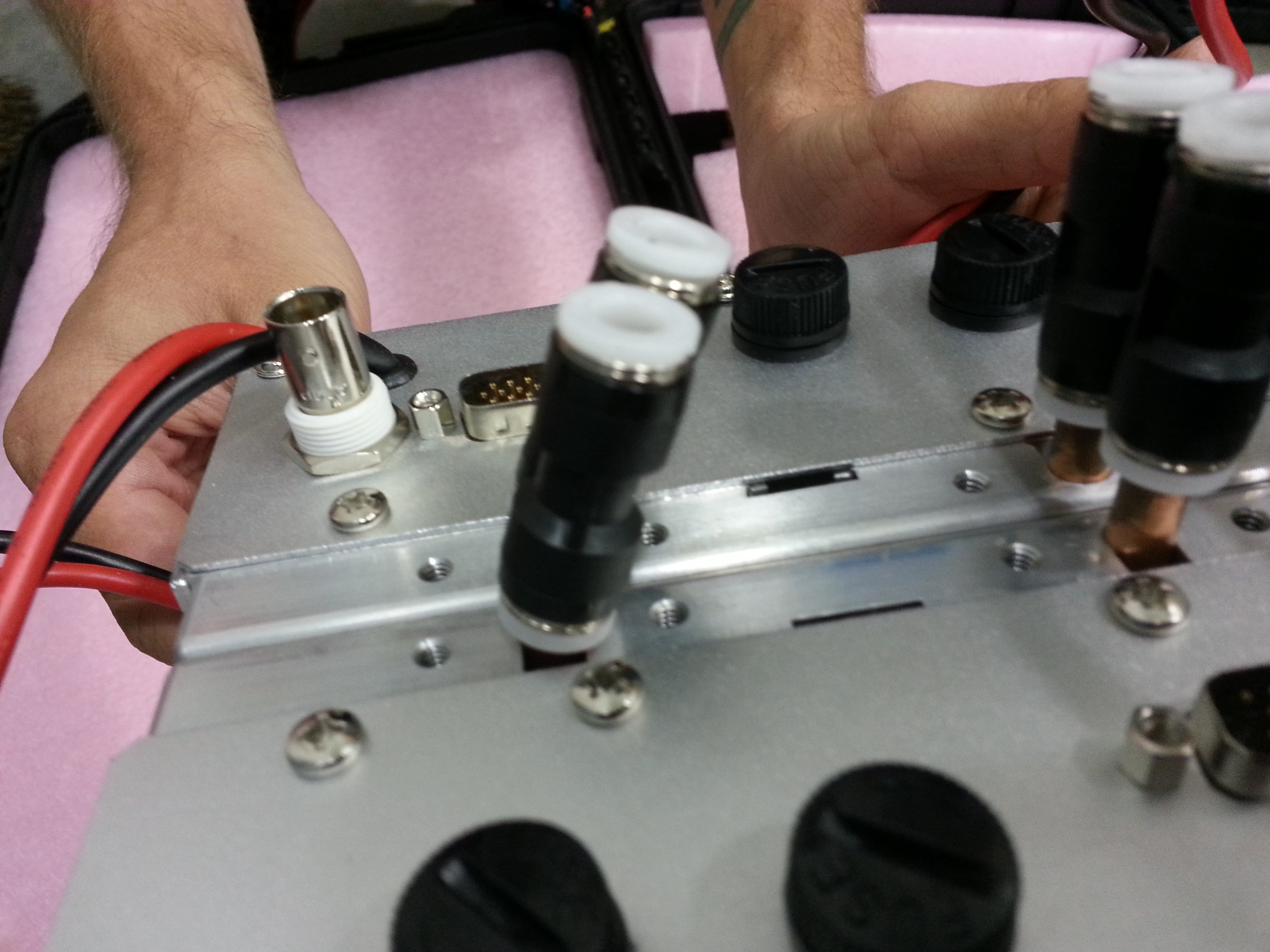
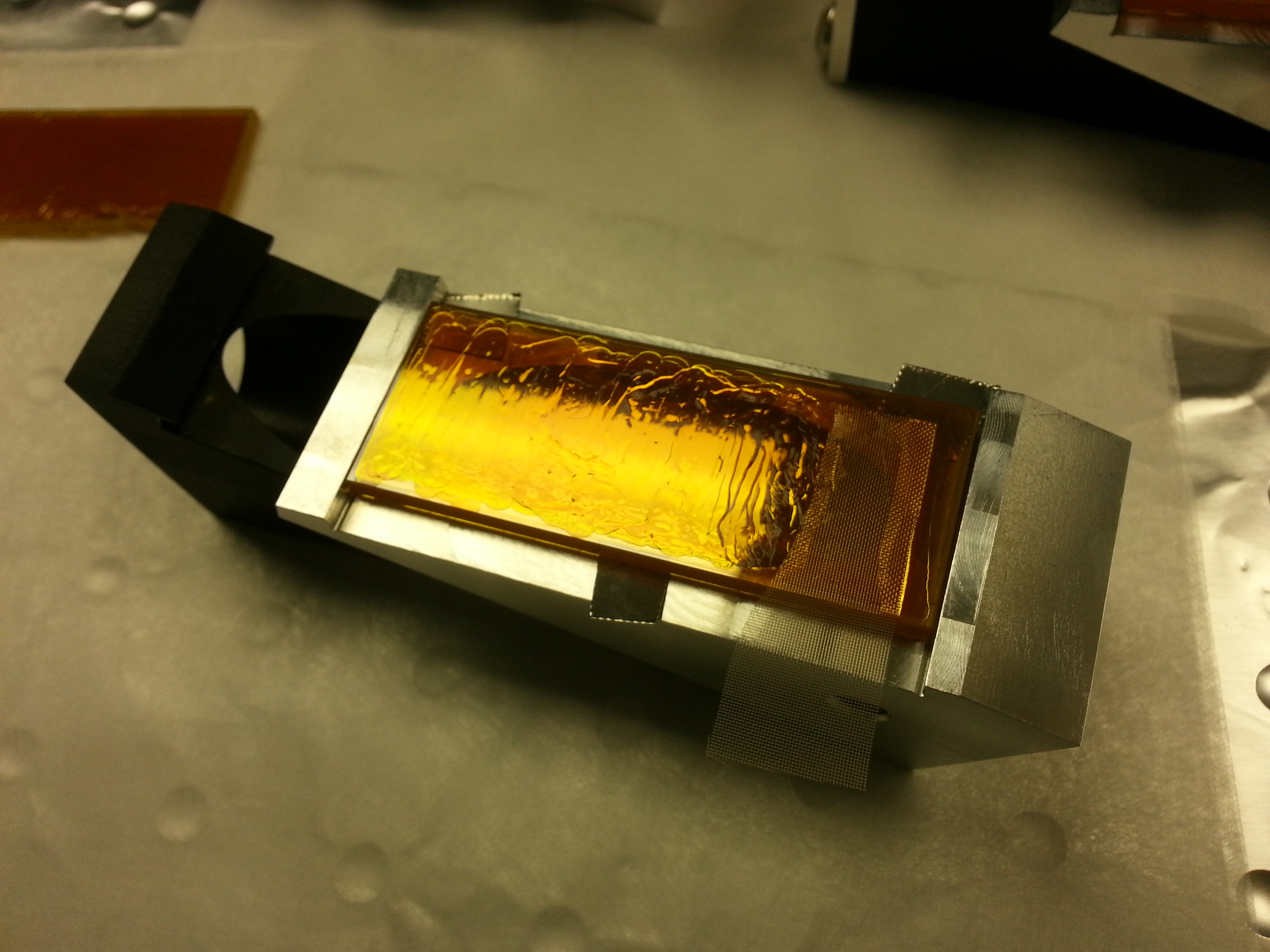
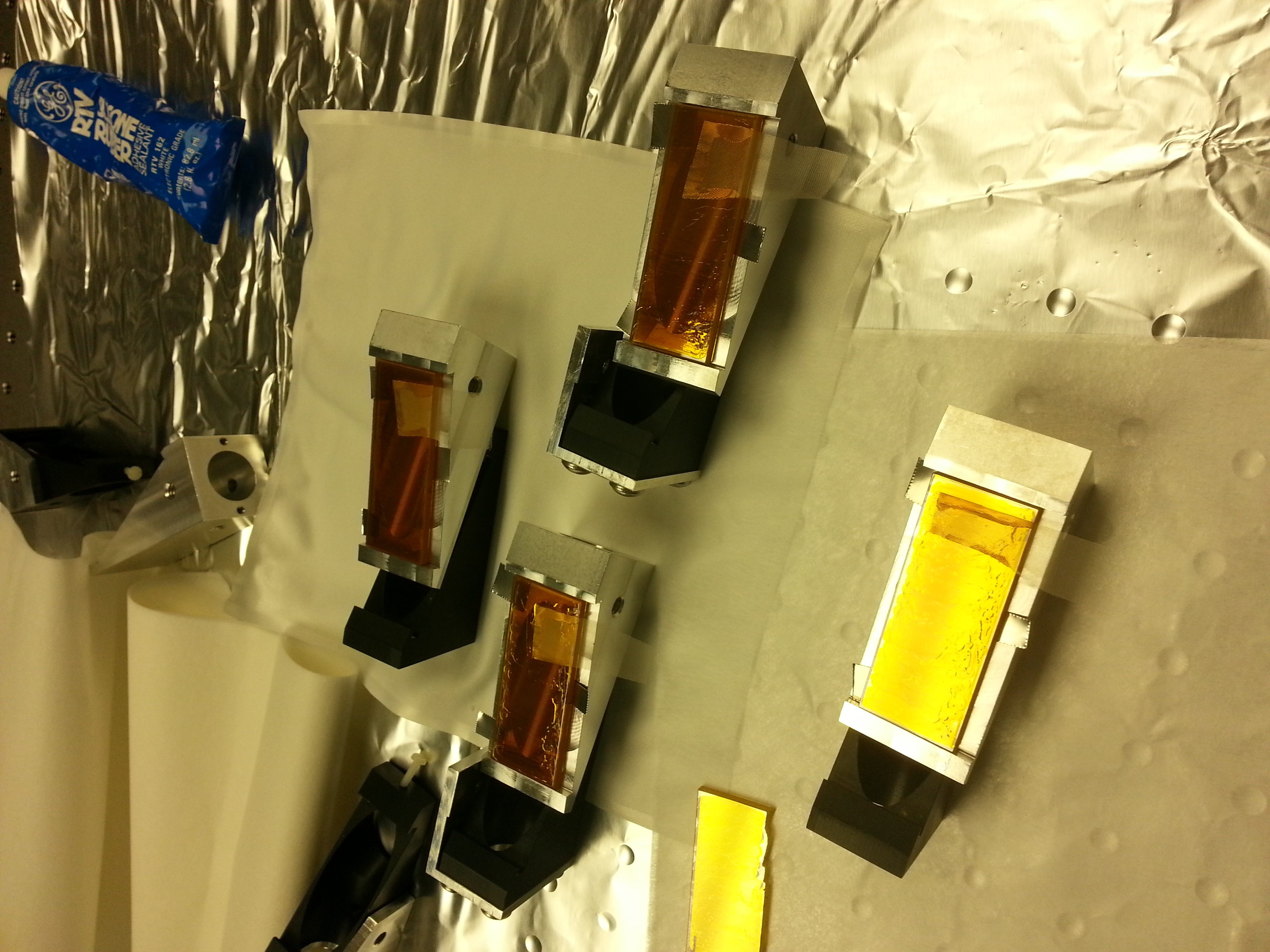
(Alastair and Greg)

Over the last three days we have worked on three separate areas:
1) Bonding the Wavelength thin film polarizers into new mounts
2) Working on the X and Y tables
3) Testing laser #20510 that arrived today from Caltech

1) Thin film Polarizer Bonding
The thin film polarizers from Wavelength, of which we use 4 per site, had pretty flimsy mounts where a plastic screw was used to hold the optic in place. This resulted in a tendency for the optic to move around causing quite large angular changes that could not be accommodated with our optical layout. A new design of mount was made and here we bond them into place.

Initially we measured the pitch of the old mounts for each of the 4 polarizers.  We measured the initial position of the optic, then tested how far it could pitch up and down.
#1) Initial position 26mRad, Highest pitch 31mRad, Lowest pitch 26mRad
#2) Initial position 18mRad, Highest pitch 31mRad, Lowest pitch 13mRad
#3) Initial position 9mRad, Highest pitch 12.5mRad, Lowest pitch 9mRad
#4) Initial position 5mRad, Highest pitch 5mRad, Lowest pitch 5mRad

The optics were then removed from their old mounts and were drag wiped. First contact was applied to the front surface to protect it during mounting. We then bonded the polarizers to the new mounts using RTV Silicone. The silicone was applied with a syringe to three points on the mount, and using 5mil spacers the optic was held with a set spacing to the mount. After 24hours (listed as max strength setting time for the RTV) the spacers were removed and the pitch of the newly bonded polarizers was measured. The mounts have 1/4-20 threads top and bottom, and we measured each polarizer both ways up to be sure that we don't have any issues with how parallel the faces are, and since the optic is on a post on a table we could also have some error from this also which we would see by checking the polarizer both ways up. Serial numbers below are those stamped on the new mounts

#001 Writing right way up 1.5mRad pitch Writing wrong way up 1.5mRad pitch
#001 Writing right way up 2.5mRad pitch Writing wrong way up 6.3mRad pitch
#014 Writing right way up 15mRad pitch Writing wrong way up 11mRad pitch
#008 Writing right way up 5.6mRad pitch Writing wrong way up 5.6mRad pitch

Polarizer #014 showed a pitch that was outside what we think acceptable (requirement 7mRad), and was then removed from the new mount and rebonded. Since we have spares we used a new mount to rule out problems it. The new mount is #015. This polarizer was tested for pitch after 4 hours of curing, but the RTV was found to not be fully cured. It was reset to the correct height and will be left the full 24hours before retesting.

2) Work on X and Y tables
The X table initially had a full version T1200007-V11 of the layout (not using masks in flipper mirrors). The Y table had most of the layout roughly in place for T1200007-V12, though mostly not aligned. The two polarizers from the power control stage had been removed from both tables for bonding.

We began by turning on the laser on the Y-arm table and aligning through the first polarizer and AOM, up to the power control stage. The extinction ratio at the first polarizer was measured at ~100:1. The AOM was checked to have a 1st order efficiency of >90%. No alignment was done after the power stage since polarizers were not available. However we did go through and mount the few missing optics in roughly the right place, so the table is complete but not aligned.

The alignment on the X-arm table should have been correct up to the power control stage, but was found to be off after the first mirror. The mount was checked and it was found to be held securely in place with the actuators locked and the mirror firmly secured. The laser mount was also checked and found to be secure. It's not clear how this had moved, but by the time the beam reached the rotation stage it was back in the correct place, so we hypothesize that the first mirror was knocked during the previous alignment and prior to its actuators being locked. We realigned the beam through the first polarizer and AOM, checking the extinction ratio of the polarizer and the efficiency of the AOM (similar values found to the Y table). The alignment was again performed up to the power control section but again the lack of polarizers meant we could go no further. This table has all its optics, but they still need placed and aligned for V12 layout (some small changes were started, but most optics have not yet been moved).

3) Testing of laser #20510
The laser that arrived from Caltech was found to have damage to the RF driver from shipping. There were three substantial pieces of damage : a dent on one side where the end of the laser had hit, and both sides of the driver had bent water connections. There were no signs of damage to the laser (you can see the linetracker on the end is straight in the photo attached, though it had clearly been hit into the RF driver) and the outside of the Pelican flight case shows no damage either.

We decided to test the laser immediately so that any repairs can be carried out. The laser was tested in the squeezer bay at the end of the LVEA, and required power, RF, water cooling etc to be put in place.

Using the driver for the laser we immediately found problems, with a maximum power output of 40W. It was found that one of the fuses on the RF driver had blown (clearly burned out and not just broken). We replaced it and immediately the fuse blew again. We then replaced the driver with a unit from a different laser. The power output was ~50W at 95% duty cycle (using synrad controller this is maximum output). The CW output should be in excess of this and matches the specs for the laser.

The RF driver will need to be returned for repair and we will be looking into improving the packaging for the lasers. There are two more lasers currently at Access having their water cooling problems repaired, and Greg may drive out to pick these up just to avoid more damage.
Images attached to this report