(Koji, Alexa, Dan)
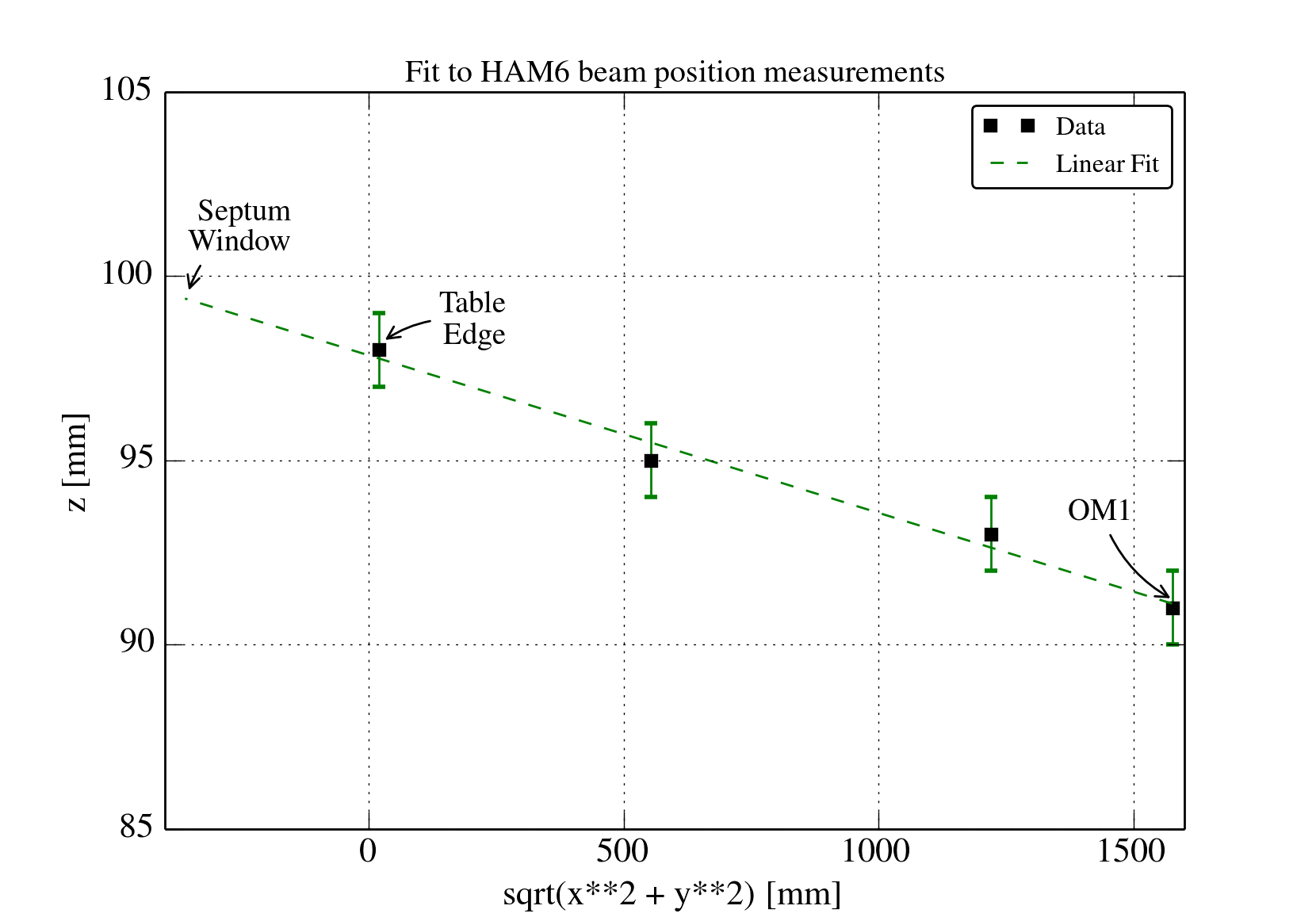
We examined the beam path in HAM6 to OM1 in order to figure out the angle of the beam. We made measurements at four different points. Using an (x, y, z) coordinate system with z = up, y = East, x = South, we find at (all in mm):
Edge of table: (20.32, 0, 98)
Intermediate point 1: (0, 552.72, 95)
Intermediate point 2: (-25.4, 1219.2, 93)
OM1: (-40.64, 1574.8, 91)
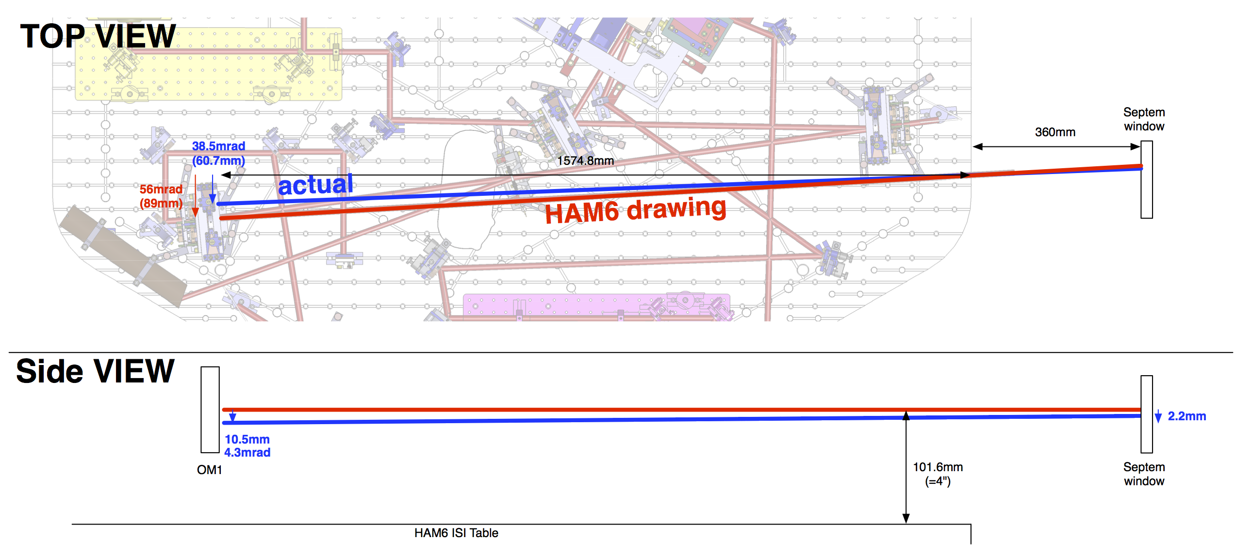
The error of the measurement in height is ±1mm, and the error along the x, y axis is ±2.5mm. The attached layout shows the original (red) beam path and the new (green) beam path. From this layout, one can see the actual vs. measured angle deviation in height and along the hoirzontal plane. Using the points above, we made a linear regression and determined the vertical angle of the beam to be 4.3 mrad. The attached plot shows the data with error bars and the linear fit.

So the situation now is this:
| angle of the beam [mrad] | position of the beam at OM1 design center [mm] | |
| PIT (positive=up) | -4.3 | -10.6 |
| YAW (positive=North) | (-39.7, though the absolute number is not that important here.) | -50.8mm |
Because of this, Koji had to tilt the OM1 up by about 4.3mrad, which is big, and I'd say that there's a high chance we will want to fix the beam angle some time in the future (e.g. larger bounce to alignment coupling). YAW is not that much of a problem because there's enough space to absorb -50.8mm.
We've been discussing how to alleviate this, and the simple hack is to rotate the septum window, which is supposed to have a 0.75deg horizontal wedge which causes 5.9mrad deflection.
According to ICS (via Joe), we should have D1101092 S/N assembly, which should have D1101005 window S/N15, which has dimension measurement that suggests 0.745deg wedge.
However, Koji measured the wedge using laser pointer and got 0.89deg which should cause 7.0mrad deflection. His measurement also suggests that the thickest side is facing south.
Now, when we rotate the septum window by X (positive=clockwise), PIT deflection was zero before but now the beam is deflected vertically by sin(X)*5.9mrad (or 7.3mrad).
Horizontally, the deflection is -5.9mrad (or -7.3) before rotation, and -cos(X)*5.9mrad (or 7.3) after, so the change in the angle would be 5.9mrad*(1-cos(X)).
If we optimize the septum rotation (which only changes by 30deg steps) for 0.75deg septum we need to rotate the septum by 120 deg clockwise.
For 0.89deg septum wedge, it would be 150deg clockwise. See below.
(The beam position change at OM1 is calculated by using 1.93m as the distance from OM1 to the septum.)
| Septum rotation (deg) |
Septum wedge (deg), and deflection (mrad) |
PIT deflection change (mrad) | PIT beam pos at OM1 (mm) | PIT beam angle (mrad) | YAW deflection change (mrad) | YAW pos at OM1 (mm) |
| 120 |
0.75, and 5.9 |
+5.1 |
-10.6+5.1mrad*1930mm |
5.1-4.3=+0.8mrad |
+5.9+2.95 =8.85 |
-50.8+8.85mrad*1930mm |
|
0.89, and 7.0 |
+6.1 |
-10.6+6.1mrad*1930 |
+6.1-4.3=+1.8mrad |
+7.0+3.5 |
-50.8+20.3mm |
|
| 150 | 0.75, and 5.9 | +2.95 |
-10.6+2.95mrad*1930 = -4.9mm |
+2.95-4.3=-1.35mrad |
+5.9+5.1 = +11.0 |
-50.8+21.2mm |
| 0.89, and 7.0 | +3.5 |
-10.6+3.5mrad*1930 = -3.8mm |
+3.5-4.3=-0.8mrad |
+7.0+6.1 = +13.1 |
-50.8+25.3mm |
Anyway, there's not much difference, but since the ICS says 0.745deg wedge, we need to rotate it by 120 deg clockwise if we decide to do it.
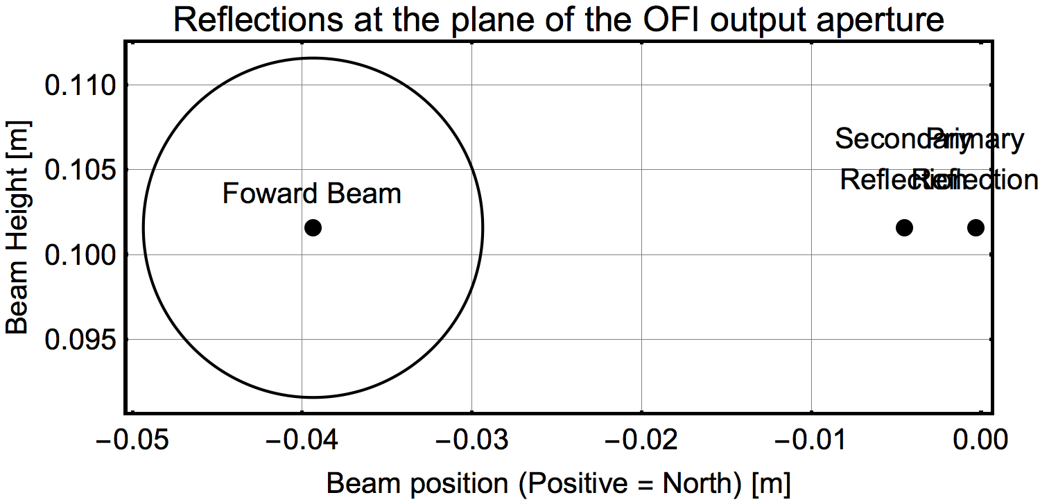
Keita and I concerned about the AR reflection from the septum. We thought we should at least check where the AR reflection goes.
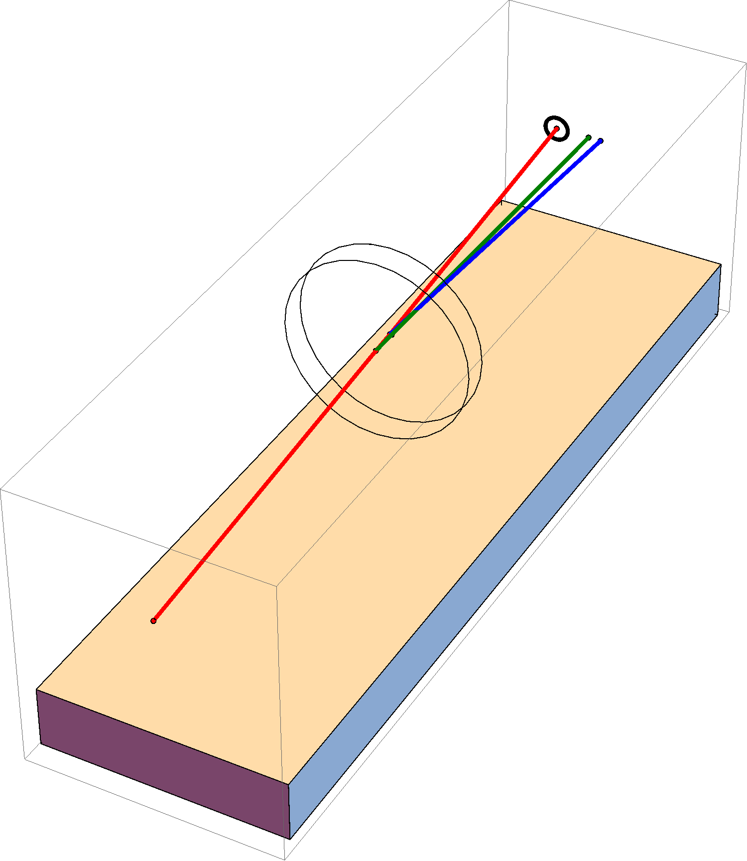
This required to make a 3D version of the ray tracing. The result is, in short, the rotation of the wedged window(by 120 or 150deg)
makes the returning beams closer to the arrangement with the nominal beams. They fly about 30-40mm North of the aperture on Faraday.
In this entry, the wedge angle of 0.75 deg is assumed.
The "nominal" beam means: "Use the HAM6 dawing. Assume this incorporates the wedging effect by the septum window."
The "actual" beam means: "Use the measured beam geometry in HAM6."
The "actual+120" and "actual+150" means: "The beams expected by rotating the septum by 120 or 150 deg in CW. The "actual" beam used for the calculation.
1st attachment is an example view of the ray tracing result.
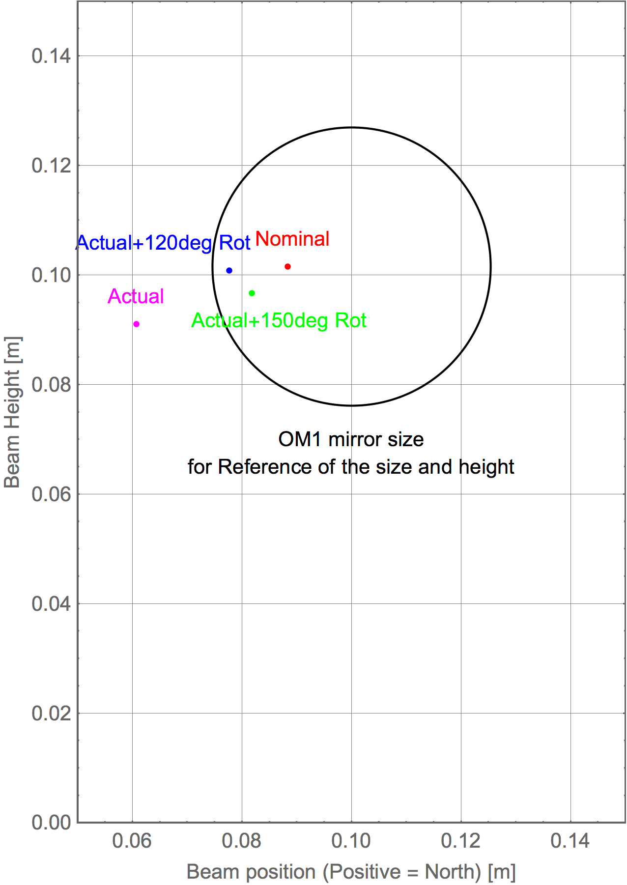
2nd attachment shows the spot positions on OM1 viewed from the back side of OM1.
Rotation of the septum by 120 deg makes the spot close to the "nominal" beam position.
"+120deg" gives us better result than "+150deg".
Note that the result I obtained here are consistent wth Keita's handwriting calculation for the OM1 spots.
3rd attachment
The beam was back-traced to HAM5. We expect that there is a 20mm aperture (iris) at 315mm from the septum window.
It is assumed that the apertue is located at the beam properly. The primary and secondary reflections are located about 35~40mm North of the aperture.
According to D0900623, these beams might be hitting the beam dump for the PBS, but not so clear.
4th attachment
This time, the actual beam was traced-back. Without rotation, the secondary beam definetely hits the apeture structure.
The primary reflction is ~30mm away from the aperture. The rotation moves the secondary reflection further away to North.
Vertical displacement is 5~10mm. So, we can say that the rotation makes the spots close to the original positions.
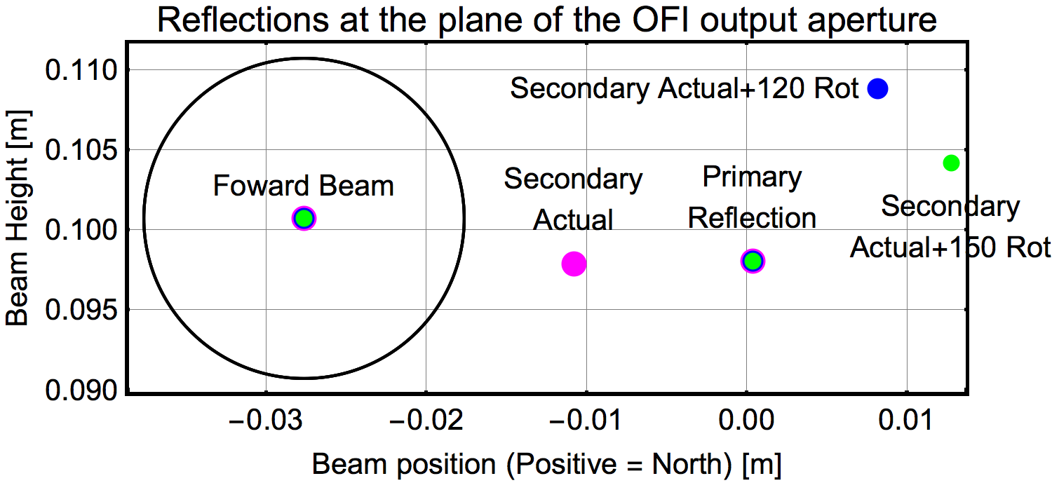
In all of these cases, it seems like all ghost beams will fall on the Faraday Isolator Refl Baffle which is mounted on the suspension cage.
https://dcc.ligo.org/LIGO-D0900136 (Output Faraday Assy)
https://dcc.ligo.org/D0902845-v5 (Faraday Isolator Refl Baffle)