Dan, Koji
After Jim finished working on the seismic platform, we checked the HAM6 electronics for ground loops. We re-discovered the grounding of the beam diverter shields in the vacuum, and found another short on the shield for the ASC-AS_C QPD. The beam diverter grounds appear to be due to the cable connector on the diverters themselves, and I think I recall that we essentially resigned ourselves to living with them. Koji fiddled with the cables and the connectors for the AS_C QPD and the ground loop went away; all of the ISC and tip-tilt connections to HAM6 are free of grounding issues. (We did not check the OMC SUS cabling, should do this tomorrow.)
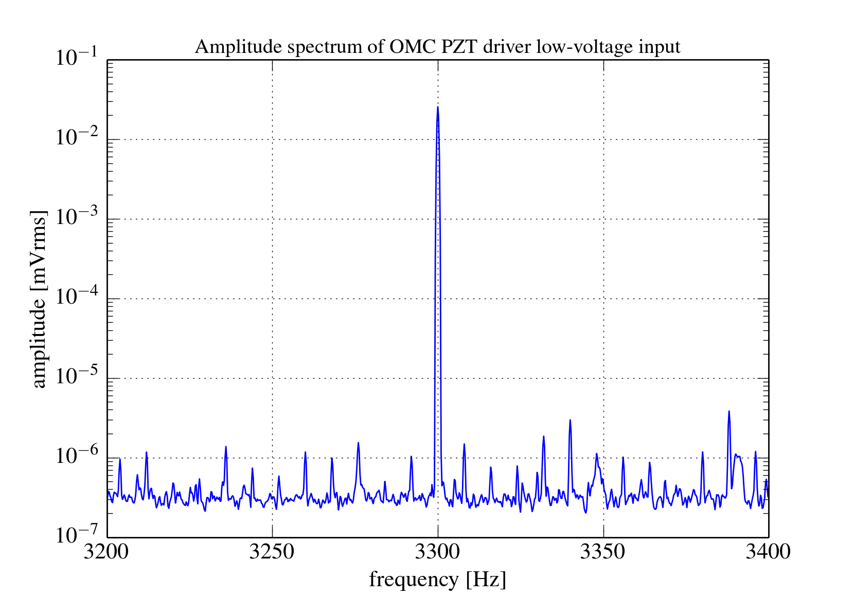
Once we finished with the ground loops we checked the dither for the OMC PZT was functional. We set the dither frequency at 3.3kHz and toyed with the amplitude while trying to understand the LV readback on the OMC control screen. The numbers didn't make much sense to us (we need to understand what's going on in the PZT driver board), but we verified that there was a signal coming out of the driver board and going into the vacuum. Tomorrow we will try to lock the OMC.
When we looked at the low-voltage PZT drive with an SR785 we immediately noticed an 8Hz comb in the spectrum, which has been observed previously at LLO. The comb is mostly at high frequency and seems to depend on the amplitude of the drive, but it's loud and messy and it's on the DAC input to the PZT driver board. The attached plot is an amplitude spectrum of the signal from the AI chassis on the input to the driver; note the units are in amplitude, not amplitude spectral density, because we were trying to understand the calibration of the digital controls. The amplitude of the dither in the plot may be much higher or much lower than what we ultimately use to control the OMC; at LLO they use 0.3V but we don't yet understand the calibration of our input signal. An oscilloscope trace of the signal leaving the PZT driver and going into the vacuum looks very noisy, with many periodic sharp glitches of ~1microsecond duration that are presumably the source of the comb in the frequency domain. (Note: the comb is also visible in the LV readback of the PZT drive, using DTT.)