[Dan, Nic, Koji]
After we tamed the OMC QPD spot motions by the alignment servo, we turned on the high voltage supply
as the vacuum pressure allowed to do that.
Then we did notice that the OMC is already locked. WHAT? Did we miss the most exciting moment!?
Well, it was okay. It was a higher order mode. We shifted the PZT offset and locked at the highest peak that gave
us about 13mA total current.
We went down to LVEA and checked the mode shape. Yes. It was TEM00.
Statement: The OMC was locked
The position of the OMC trans spot was checked at ISCT6. Unfortunately the spot was hitting a pillar of the ISCT6 enclosure.
It is not nice to make a hole on the pillar. We probably need to move the table and think carefully how to connect the tube
to the table enclosure...
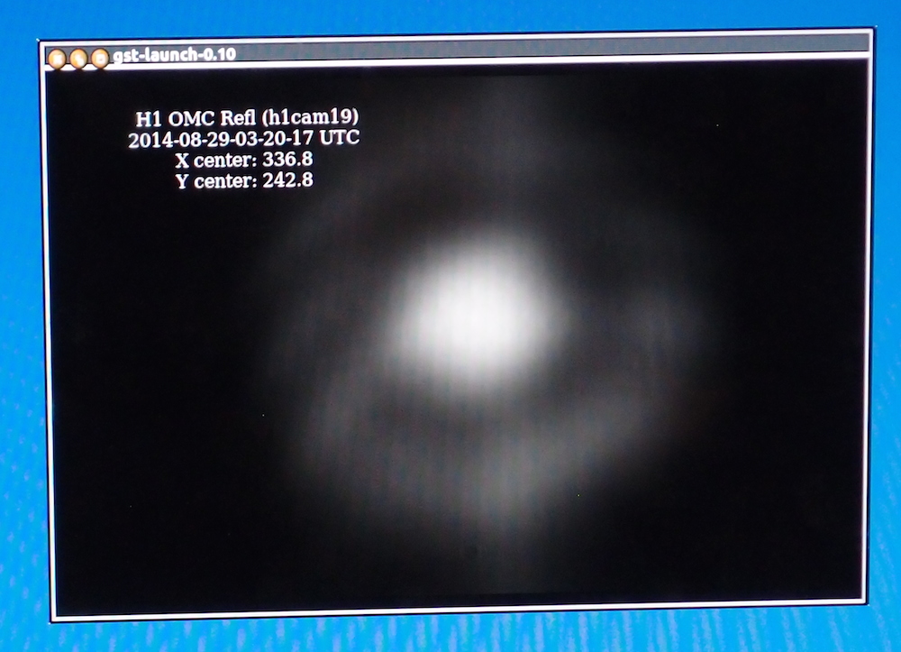
The OMC REFL with the best alignment looked a bull's eye as we suspected (attached photo #1). Dan is now measuring the mode scan for the mode matching ratio.
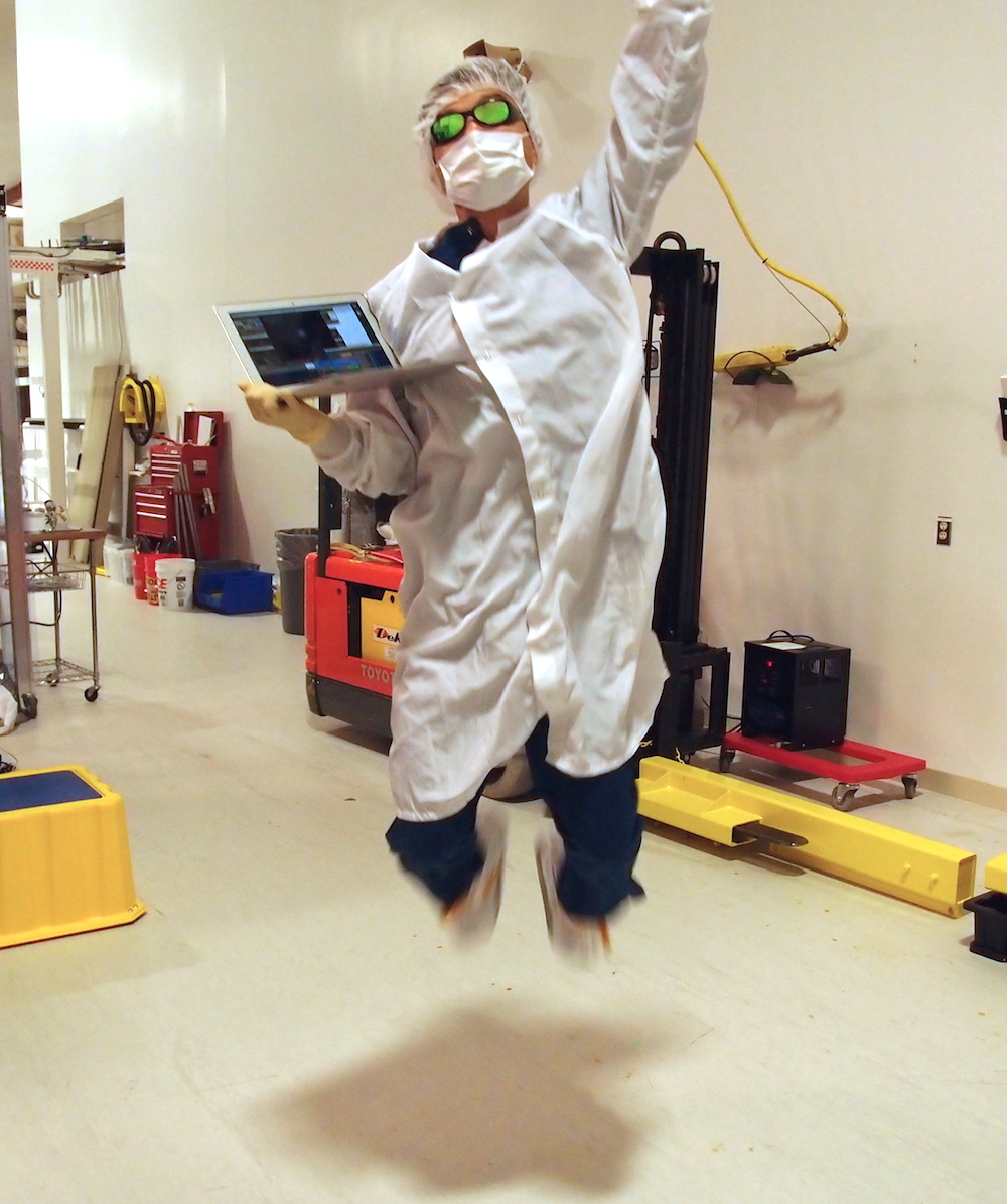
For the celebration, Nic cut open an OMC locking cantaloupe. Thanks Gerardo!

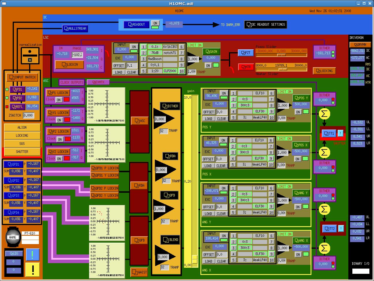
Title: gains moved around in OMC servo
The OMC NORM output was not ~1.0, this was because the input to the normalization was less than 0.1, and the denominator has a lower saturation at that point.
I put a gain of 10 into 'H1:OMC-DCPD_NORM_FILT_GAIN' and 'H1:OMC-DCPD_NORM_GAIN'. Thus bringing the denominator above 0.1 and allowing the normalization to work. There was a gain of 1000 in 'H1:OMC-DCPD_NORM_GAIN' which I moved into 'FM8' of 'H1:OMC-LSC_SERVO' (called 60dB).
Finally, the gain change due to the normalization fix had to be corrected by putting a gain of 1 into 'H1:OMC-LSC_SERVO_GAIN'.
Old pictures.
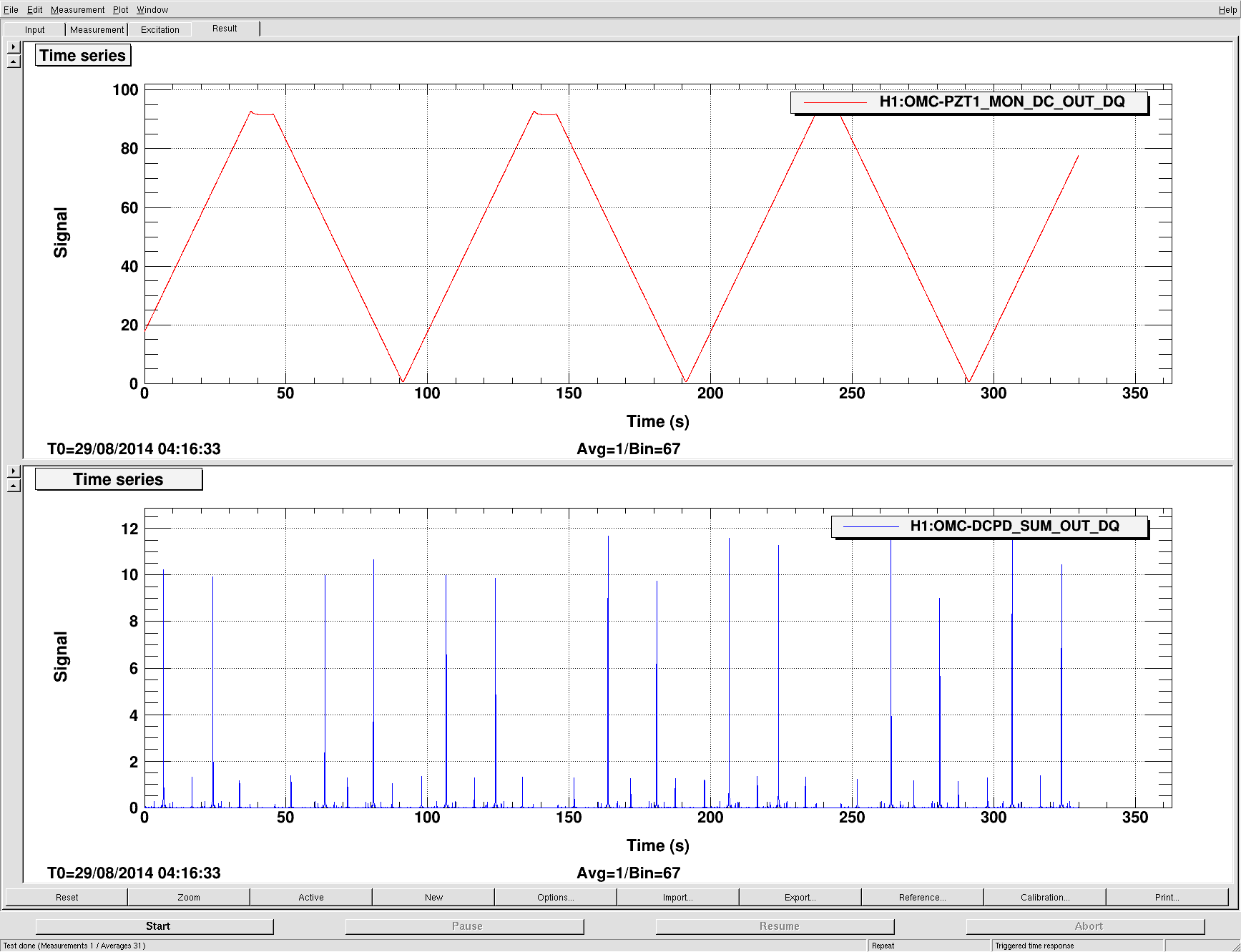
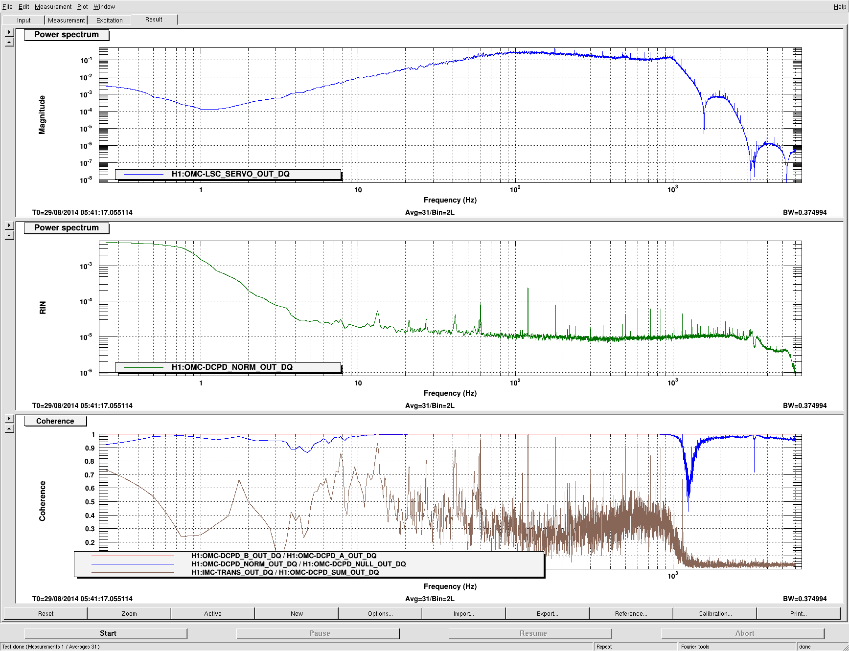
Here are images of a mode-scan of the OMC, and spectra that show the control signal, the normalized DCPD Sum (called DCPD Norm, in units of RIN), and coherence between some interesting channels. The noise on the DCPDs is limited by the OMC, not the intensity noise from the IFO; only a little bit of the noise on IMC_TRANS is making it to the DCPDs. Note that the ISS is currently disabled. The two DCPDs are coherent so we're not shot-noise limited.
I took 60-second averages of the sum of OMCR_A with the OMC locked and unlocked. Unlocked the sum was 9316.68, locked was 1834.33. The visibility/mode-matching into the OMC is about 80%. (A small but nonzero fraction of this is due to the power in the sidebands, the modulation depth is 0.3.)
A text file for the mode scan can be found here. The columns are [time, PZT_VMON, DCPD_SUM].
Note, all of this data was taken with a single bounce off ITMX., with one stage of whitening on the DCPDs.
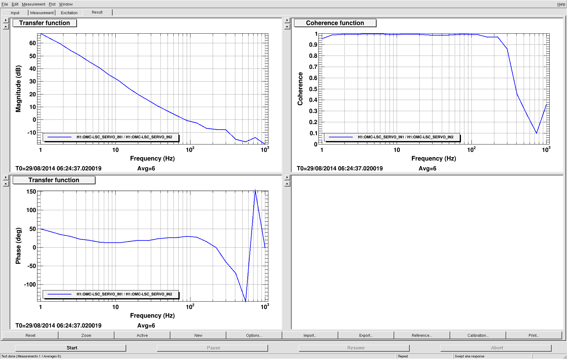
Also I've attached a figure of the OMC open-loop gain measurement. UGF is 90Hz.
Nice!
A few things in reply to Dan's comment:
1) I wonder why the mode scan looks so messy. Ramping the PZT over the full range should deform the cavity slightly, so we usually see a couple-percent difference in transmission from mode to mode, but the variation seems much wider here. Was the alignment not stable? Also, what's going on with those PZT readback saturations?
2) Was this RIN plot from before the NORM calibration was fixed? If not, it seems crazy high. It looks like your input beam is pretty noisy, since you see some coherence with IMC TRANS, but I guess this is somewhat expected at lower frequencies with ISS off. However, there is no way the OMC should be adding noise at that level.
3) Now would be a good time to balance the DCPDs. I believe Keita made a precise measurement of the electronic TFs which can be used for frequency-dependent correction, and then Koji should have the responsivity numbers for the diodes. Those should take care of most of the difference, and then the rest can be done with the balance slider (we needed 0.6% gain bias at LLO). The easiest way to do this is to put an intensity modulation line in and cancel it in the NULL signal.
I believe this was done with a single bounce of ITMX.
ITMY had an oplev issue at the time as you can seen in https://alog.ligo-wa.caltech.edu/aLOG/index.php?callRep=13654