[Dan, Nic, Koji]
Summary
The OMC alignment servo was commissioned today.
- The sensing matrix (between OM1/2/3 P/Y to OMC QPD A/B P/Y) was measured.
- From OM3 to OMC QPD A/B measurement, the ratio of the spot sizes on the QPDs were inffered.
-
From the geometry of the OMC and the spot size ratio, the alignment input matrix was set
such that the beam angle and position with regard to the beam waist becomes the servo basis. -
From the sensing matrix measurement and the input matrix, the output matrix was set such that the actuation is diagnalized in terms of the servo basis.
- The servo loops were engaged and the spot on the QPDs were successfully controlled.
To Do
- Open loop TF measurements
- Noise measurement (inloop & free running)
- Servo shape tuning
- Confirmation of the servo diagonalization
- Dither alignment implementation
1. Sensing matrix
The ISC alignment input of OM1/2/3 was excited at 3.9Hz and 2.9Hz for Pitch and Yaw, respectively.
The spot motion was read out by QPDA and QPDB.
Measured sensing matrix was
| H1:OMC-ASC_QPD_A_PIT_OUT |   | -2.21e-3 +3.05e-3 -1.35e-3 || H1:SUS-OM1_M1_LOCK_P_IN1 |
|                          | = |                            || H1:SUS-OM2_M1_LOCK_P_IN1 |
| H1:OMC-ASC_QPD_B_PIT_OUT |   | -1.05e-3 -1.64e-3 -6.24e-4 || H1:SUS-OM3_M1_LOCK_P_IN1 |

| H1:OMC-ASC_QPD_A_YAW_OUT |   | +1.11e-3 -3.13e-3 +1.84e-3 || H1:SUS-OM1_M1_LOCK_Y_IN1 |
|                          | = |                            || H1:SUS-OM2_M1_LOCK_Y_IN1 |
| H1:OMC-ASC_QPD_B_YAW_OUT |   | -6.38e-4 -1.86e-3 -9.55e-4 || H1:SUS-OM3_M1_LOCK_Y_IN1 |
2. Spot size ratio
Since OM3 is a flat mirror it is straight forward to use it as a scanner to infer the beam size on the QPDs.
Unfortunately, I don't have the absolute calibration of the OMs, only the ratio of the beam size was obtained.
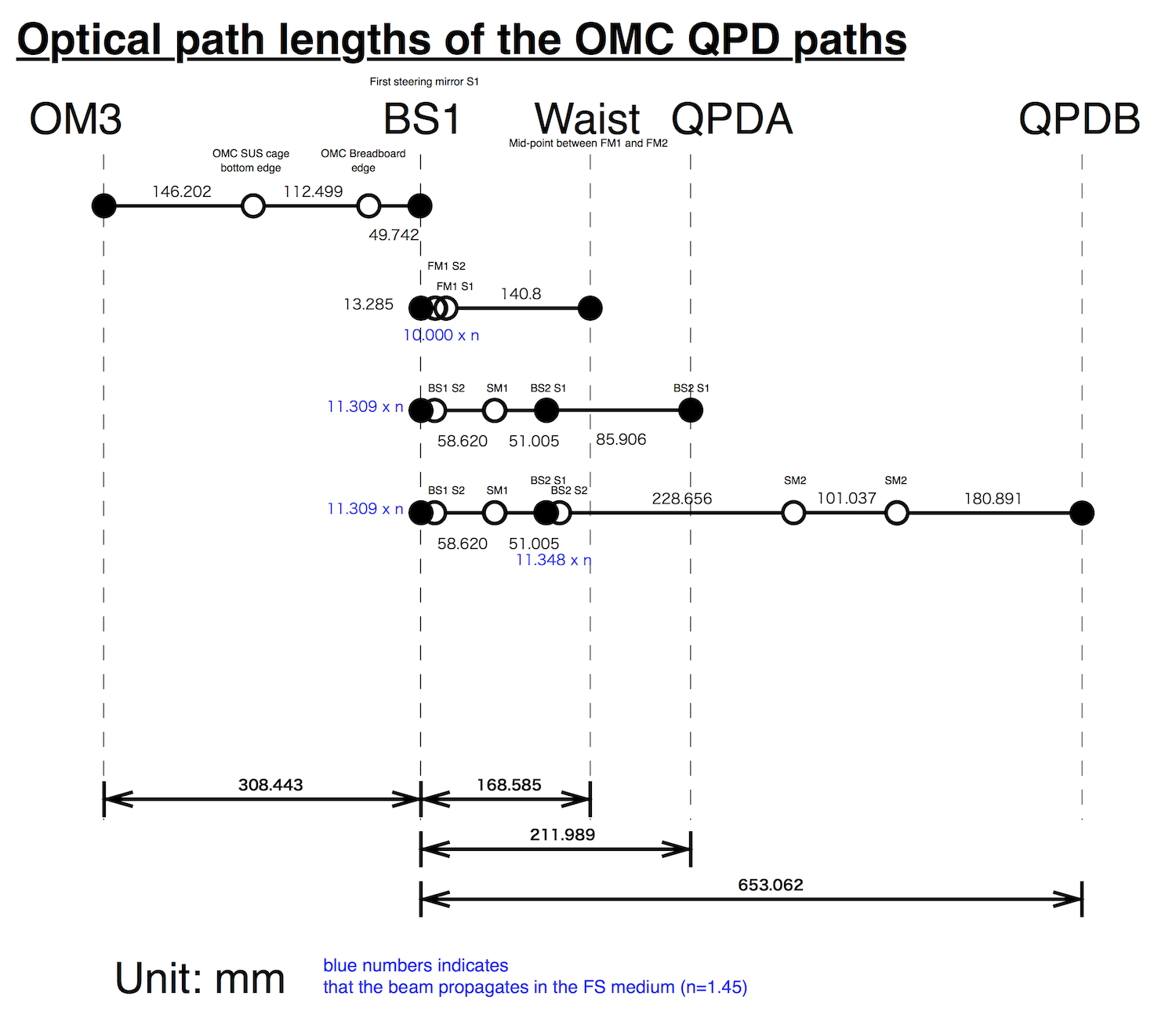
The geometrical arrangement of the QPDs and OM3 are found in the attachement.
(H1:OMC-ASC_QPD_A_PIT_OUT) = Sqrt(2/Pi)/omega_A * [(2 L_QPDA) * A_OM3_PIT(f) * (H1:SUS-OM3_M1_LOCK_P_IN1)]
(H1:OMC-ASC_QPD_B_PIT_OUT) = Sqrt(2/Pi)/omega_B * [(2 L_QPDB) * A_OM3_PIT(f) * (H1:SUS-OM3_M1_LOCK_Y_IN1)]
3. Input matrix
(TO BE FILLED)
4. Output matrix
(TO BE FILLED)
5. Servo control
The servo filter did not have the slow integrator which surpresses the DC component. An integrator below 0.1Hz was added to FM6.
Attached are two plots:
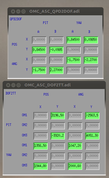
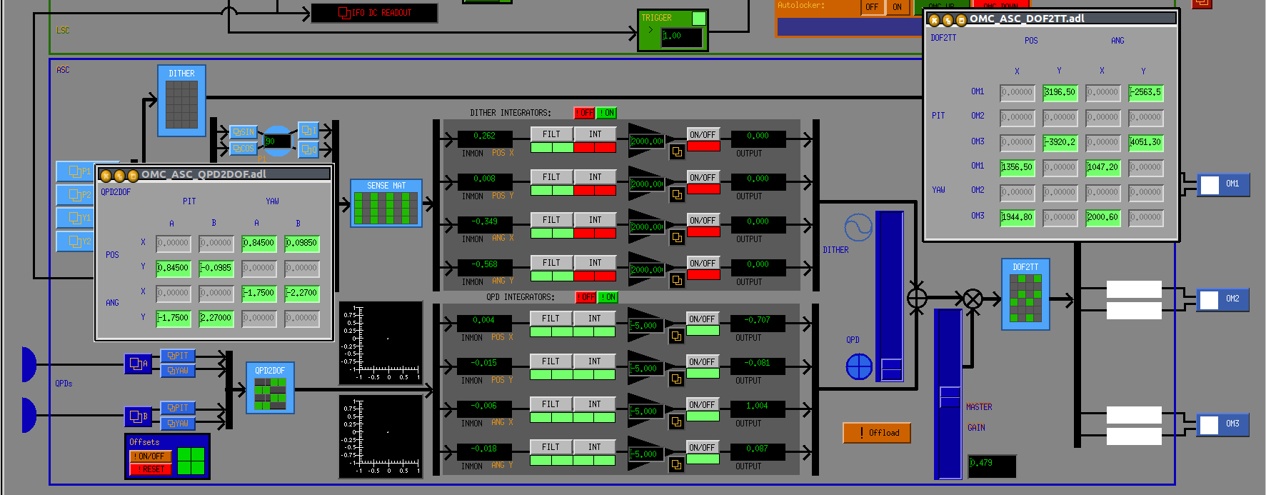
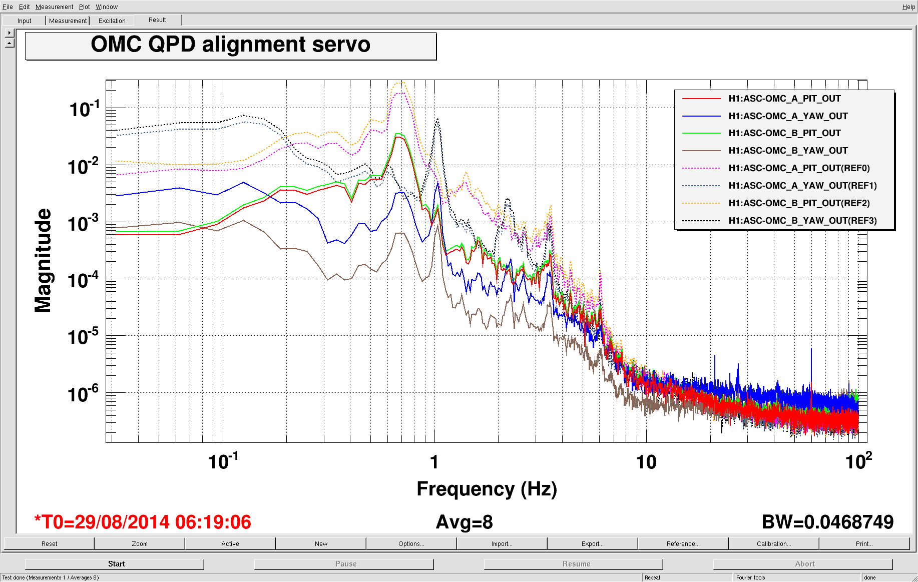
- screenshot of QPD servo settings with sensing and actuation matrices
- screenshot of OMC QPD signals showing the loop suppression. Dashed references are with the loops open, current traces are loops closed. We get about a factor of ten below a few Hz, we can do better!
Note: if the gain slider is set too high (more than ~0.3, with the current loop settings) then the servo actuation begins to saturation the DAC output to the OM3 coil driver.
[Dan, Nic, Koji]
The detailed description of the calculation had been missing. And we found a mistake in calculating the output matrix.
Here is the updated version of the matrices. This new setup should be tested when the IFO time is available.
In addition, we are going to update the calibration so that the servo inputs show the beam displacement and angle
in um and urad.
1. Sensing matrix
The ISC alignment input of OM1/2/3 was excited at 3.9Hz and 2.9Hz for Pitch and Yaw, respectively.
The spot motion was read out by QPDA and QPDB.
Measured sensing matrix was
| H1:OMC-ASC_QPD_A_PIT_OUT |   | T_OM1P_QAP T_OM2P_QAP T_OM3P_QAP || H1:SUS-OM1_M1_LOCK_P_IN1 |

	|                          | = |                                  || H1:SUS-OM2_M1_LOCK_P_IN1 |

	| H1:OMC-ASC_QPD_B_PIT_OUT |   | T_OM1P_QBP T_OM2P_QBP T_OM3P_QBP || H1:SUS-OM3_M1_LOCK_P_IN1 |


	                               | -1.05e-3 -1.64e-3 -6.24e-4 || H1:SUS-OM1_M1_LOCK_P_IN1 |

	                             = |                            || H1:SUS-OM2_M1_LOCK_P_IN1 |

	                               | -6.38e-4 -1.86e-3 -9.55e-4 || H1:SUS-OM3_M1_LOCK_P_IN1 |


	| H1:OMC-ASC_QPD_A_YAW_OUT |   | T_OM1Y_QAY T_OM2Y_QAY T_OM3Y_QAY || H1:SUS-OM1_M1_LOCK_Y_IN1 |

	|                          | = |                                  || H1:SUS-OM2_M1_LOCK_Y_IN1 |

	| H1:OMC-ASC_QPD_B_YAW_OUT |   | T_OM1Y_QBY T_OM2Y_QBY T_OM3Y_QBY || H1:SUS-OM3_M1_LOCK_Y_IN1 |


	                               | -2.21e-3  3.05e-3 -1.35e-3 || H1:SUS-OM1_M1_LOCK_Y_IN1 |

	                             = |                            || H1:SUS-OM2_M1_LOCK_Y_IN1 |

	                               |  1.11e-3 -3.13e-3  1.84e-3 || H1:SUS-OM3_M1_LOCK_Y_IN1 |
Here we define the combined matrix T:
T=

	| T_OM1P_QAP T_OM2P_QAP T_OM3P_QAP 0          0          0          |

	| T_OM1P_QBP T_OM2P_QBP T_OM3P_QBP 0          0          0          |

	| 0          0          0          T_OM1Y_QAY T_OM2Y_QAY T_OM3Y_QAY |

	| 0          0          0          T_OM1Y_QBY T_OM2Y_QBY T_OM3Y_QBY |
2. Spot size ratio
Since OM3 is a flat mirror it is straight forward to use it as a scanner to infer the beam size on the QPDs.
When the QPD signals are normalized by the sum, the pitch and yaw output signals becomes proportional to
the spot displacement normalized by the spot size. i.e. Intensity distribution
I(x) = sqrt(2/pi)/w Exp[-2 (x-dx)^2/w^2]
gives us the signal
s(dx) = Int_(-Infinity)^0 I(x) dx + Int_0^(Infinity) I(x) dx

	      = Erf(sqrt(2) dx / w)
ds/dx|dx=0 = sqrt(8/pi)/w
Therefore
(H1:OMC-ASC_QPD_A_PIT_OUT) =   Sqrt(8/Pi)/wA * [(2 L_QPDA) * theta_OM3_PIT(f) * (H1:SUS-OM3_M1_LOCK_P_IN1)]

	(H1:OMC-ASC_QPD_B_PIT_OUT) =   Sqrt(8/Pi)/wB * [(2 L_QPDB) * theta_OM3_PIT(f) * (H1:SUS-OM3_M1_LOCK_P_IN1)]


	(H1:OMC-ASC_QPD_A_YAW_OUT) =   Sqrt(8/Pi)/wA * [(2 L_QPDA) * theta_OM3_YAW(f) * (H1:SUS-OM3_M1_LOCK_Y_IN1)]

	(H1:OMC-ASC_QPD_B_YAW_OUT) = - Sqrt(8/Pi)/wB * [(2 L_QPDB) * theta_OM3_YAW(f) * (H1:SUS-OM3_M1_LOCK_Y_IN1)]
Here wA and wB are the spot size at QPDA and QPDB, L_QPDA and L_QPDB are the lever length from OM3 to each QPD,
and theta_OM3_PIT(f) and theta_OM3_YAW(f) are actuator response of OM3 from the actuator count to the physical angles,
respectively.
Note that the negative sign for the fourth formula comes due to odd number of reflecting optics in the
OMC QPDB path.
Unfortunately, the absolute actuator calibration of theta_OM3_PIT(f) and theta_OM3_YAW(f) were not known.
Also, because of the mode mismatch, we don’t know actual wA and wB. Therefore we decided to compensate
the difference of the spot size between QPDA and QPDB.
Using the optical path length diagram, we obtained L_QPDA = 0.520 [m] and L_QPDB = 0.962 [m]
(wB/wA)_PIT = (T_OM3P_QAP / L_QPDA) / (T_OM3P_QBP / L_QPDB) = -6.24e-4 / -9.55e-4 * 0.962/0.520 = 1.21
(wB/wA)_YAW = - (T_OM3Y_QAY / L_QPDA) / (T_OM3Y_QBY / L_QPDB) = -(-1.35e-3) / 1.84e-3 * 0.962/0.520 = 1.35
We took the average of these two values and used 1.3 as w_B/w_A.
3. Input matrix
We want to convert the basis of the signal from QPD basis to the beam angle/position basis with regard to the waist:
| (H1:OMC-ASC_QPD_A_PIT_OUT) |        | wB/wA   0  | | 1  L_QPDA_WAIST | | V_POS |

	|                            | propto |            | |                 | |       |

	| (H1:OMC-ASC_QPD_B_PIT_OUT) |        |   0     1  | | 1  L_QPDB_WAIST | | V_ANG |
| (H1:OMC-ASC_QPD_A_YAW_OUT) |        | wB/wA   0  | | 1  L_QPDA_WAIST | | H_POS |

	|                            | propto |            | |                 | |       |

	| (H1:OMC-ASC_QPD_B_YAW_OUT) |        |   0    -1  | | 1  L_QPDB_WAIST | | H_ANG |
Again the additional negative sign for the QPDB YAW comes from the odd number of mirrors in the OMC QPDB path.
Looking at the diagram attached to the original entry the distances from the QPDs to the waist position
are L_QPDA_WAIST = 0.0434 and L_QPDA_WAIST = 0.484. Taking the inverse matrices of the right hand side,
we obtain
| V_POS |        |  0.845 -0.0985 | | (H1:OMC-ASC_QPD_A_PIT_OUT) |

	|       | propto |                | |                            |

	| V_ANG |        | -1.75   2.27   | | (H1:OMC-ASC_QPD_B_PIT_OUT) |


	| H_POS |         |  0.845  0.0985 | | (H1:OMC-ASC_QPD_A_YAW_OUT) |

	|       | propto |                | |                            |

	| H_ANG |         | -1.75  -2.27   | | (H1:OMC-ASC_QPD_B_YAW_OUT) |
i.e.
| H_POS |        |  0      0       0.845  0.0985 | | (H1:OMC-ASC_QPD_A_PIT_OUT) |

	 | V_POS |        |  0.845 -0.0985  0      0      | | (H1:OMC-ASC_QPD_B_PIT_OUT) |

	 |       | propto |                               | |                            |

	 | H_ANG |        |  0      0      -1.75  -2.27   | | (H1:OMC-ASC_QPD_A_YAW_OUT) |

	 | V_ANG |        | -1.75   2.27    0      0      | | (H1:OMC-ASC_QPD_B_YAW_OUT) |
This matrix is defined as IN.
4. Actuator selection
Which mirror combination we should use? Nic and Dan checked Gouy phase at the location of the mirrors.
That suggested that OM2 and OM3 has -70deg and +70deg with regard to the Gouy phase at OM1. Therefore
we decided to use OM1 and OM3. That means we convert 4 inputs to 6 outputs using the following ACT matrix.
      | 1 0 0 0 |

	      | 0 0 0 0 |

	      | 0 1 0 0 |

	ACT = |         |

	      | 0 0 1 0 |

	      | 0 0 0 0 |

	      | 0 0 0 1 |
5. Output matrix
Now we want to set the output matrix to make the roundtrip open loop matrix diagonal.
That means we want to make
IN.T.ACT.OUT = I
i.e.
OUT = Inverse(IN.T.ACT)
We want to make the actuation orthogonal in terms of the POS/ANG basis. In order to obtain the
actuation matrix, we need to take the inverse of the product of the matrix in 3. and 1.
OUT = Inverse[IN.T] =

	|    0  -1019     0   410 |

	|    0  - 369     0  -781 |

	| -405      0   214     0 |

	| -301      0  -392     0 |
The actual output matrix of the MEDM screen is a combination of ACT and OUT, that is
          |    0  -1019     0   410 |

	           |    0      0     0     0 |

	           |    0  - 369     0  -781 |

	 ACT.OUT = |                         |

	           | -405      0   214     0 |

	           |    0      0     0     0 |

	           | -301      0  -392     0 |
6. Servo control
The servo filter did not have the slow integrator which suppresses the DC component.
An integrator below 0.1Hz was added to FM6.