This is a report from yesterday
In the afternoon of yesterday, Sheila noticed that the POPAIR_B_RF18 did not reach a high value in the PRMI no matter how she steered IM4, PRM and PR2. So I tried looking for the cause. Then I found two clipping issues as follows:
-
The in-air POP beam was clipped at the bottom periscope mirror of ISCT1.
- I realigned the optics on the table. This increased the POP_RF18 from 60 uW to 80 uW.
-
The in-air POP camera showed a clipped beam image, which I could not identify where this happened. But it smelled like a intra-cavity clipping.
- This persisted even after I fixed the periscope bottom mirror on ISCT1.
- Steering a combination of PR2 and PR3 allowed me to improve the clipped image.
- Steering PR2 and PR3, I could increase the POP18 power to 160 uW which is higher than what we usually have (~ 120 uW). The image on the POP camera improved.
- Also this must have increased the actual cavity power build up because both LSC-MICH and PRCL servos started oscillating due to a too-high-UGF as I steered the PRs.
The work will continue in parallel to the main DRMI lock project.
(Some detailed notes)
* POPAIR_B_ calibration changed
In the process, I found the POPAIR_B_RF18 saturating at its ADC. So I decreased the whitening gain to 24 dB from 33 dB. Also I changed the FM9 of POPAIR_B_RF18 in order to maitaing the same calibrated numbers. Now POP18 does not saturate. Also, I noticed that the demodulation phase was not quite good. So I rotated it from -100 to -113 deg. This increased the RF18_I power by a few percent.
* Clipping on ISCT1
The clipping on the ISCT1 bottom periscope was due to the beam at too low height. Also the horizontal position was off toward north by roughly a beam spot size. I could not precisely assess the spot position on the upper periscope mirror because of a narrow available space in the ISCT1 enclosure. But, with a sensor card, it did not seem clipped at the upper periscope. The image below is a POP camera before I improved the two clipping issues:
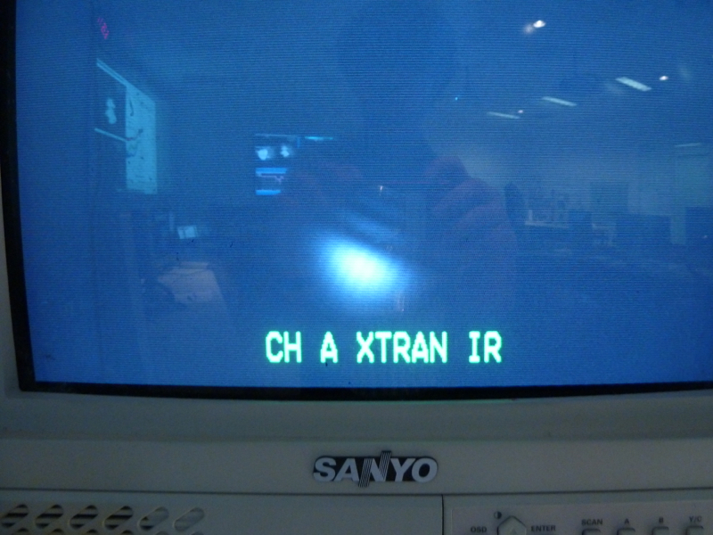
Since the camera does not have a TV lens, the image is up-side-down and right side left. It is clear that the beam is clipped in its lower part (or upper part on the camera view). However, fixing the bottom periscope mirror situation did not change the beam image. This is how I found another clipping issue.
* Steering PR2 and PR3
I wanted to move the (back propagating) POP beam in pitch to see how the clipping situation changes. Since touching IM4, PRM and PR2 did not seem to give a significant effect on the clipped image, I started using PR3. Note that before I touched PR3, it was right on the center of the oplev QPD. I have moved PR3 toward the positive side in the suspension bias slider. At the same time, in order to maintain a high build up, I moved PR2 toward the negative side in the bias slider. So this operation is equivalent to an introduction of translation in the beam line between ITMX and PR3 downward while mantaining the same spot on PRM and PR2. Also, this alignment operation introduced a tilit in the beam line between PR3 and PR2 such that the forward propagating beam goes downward as it approaches to PR3 from PR2. Note that looking at the PR3 GigE camera, I noticed that the beam spot was a bit too-low on the mirror from the beginning. Unfortunately I could not see a spot on the BS because of the too low power in the PRC.
As I improved the clipped image and the POP18 power, both MICH and PRCL servo started oscillating due to a too high UGF. I derecased both of them by 40% rom the nominal guardian-commanded gains in order avoid the servo instabilities. i did not get a chance to check the open loop transfer functions.
We should carefully study what this means. Does it mean the spot position on PR3 and ITMX matters ? Or, the angle of the beam line between PR2 and PR3 matters ?