daniel.hoak@LIGO.ORG - posted 20:41, Monday 22 September 2014 - last comment - 09:26, Tuesday 23 September 2014(14083)
weekend OMC work
On Sunday I took advantage of the interferometer downtime to make some improvements to the OMC scripts:
- The script to offload the OMC alignment outputs to the OM bias sliders has been re-written in python and now uses the outputs of the DRIVEALIGN matrix as the control signals. This has the advantage of using the control signals *after* they have gone through the angle-to-angle decoupling. (Sad thing: since the DRIVEALIGN matrix only decouples the ISC signals, some residual A2A coupling will reappear after the ISC signals are offloaded to the sliders.)
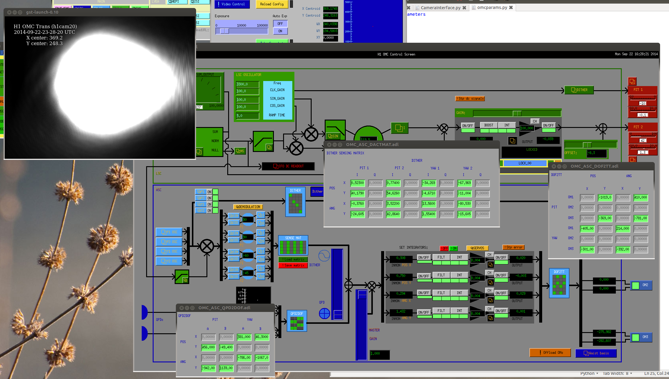
- The sensing matrix for the OMC dither alignment loops was re-measured. This was done using DC offsets in the POS and ANG filters while the QPD alignment was engaged. The matrix was inverted and plugged into the dither SenseMat. With the dither loops engaged we gain about 5% in DCPD SUM, but the loops have a time constant of a few seconds and don't suppress the motion around 1Hz. I didn't have a chance to measure the loop shape or take another mode scan, or investigate the OMC length noise. These are on the to-do list.
- Before measuring the sensing matrix I spent a little time checking the amplitude of the dither lines and the goodness of the demodulated signals. I adjusted the amplitudes so that all four dither lines are about a factor of two lower than the saturation point of the tip-tilt DACs. I'm not sure how to optimize these amplitudes (same goes for the SINE and COSINE gains in the oscillator controls), but things are working, and they have some headroom. There was a lot of noise in the dither error signals above 10Hz, and I found that the OM DACs would saturate from the dither control signals. Since these loops are unlikely to have a UGF above 1Hz, I inserted some filters to suppress the control signals above 10Hz (see OM1_dither_sat, attached). This kept the DACs from saturating, but it's a hacky fix and we should take a closer look.
- I rotated the demodulation signals so that the signal from a DC offset in POS or ANG is maximized in the I-phase. The yaw loops needed some rotation, not sure why these would be different from pitch?
Also, last week I investigated a few bugs in the OMC PZT driver board:
- Previously we had observed the HV readback from the OMC PZT driver was hitting the rail at about 90V. This was due to the driver hitting the current limit in the HV supply; the current limit was set at 1.010mA and the board needs about 1.025mA to deliver the full 100V to PZT2. In consultation with Koji and Rich, Richard and I increased the current limit to 4mA. (In an abundance of caution, I checked that the PZTs were not shorted [and only capacitvely coupled] by measuring their resistance at the vacuum flange. They're fine.)
- Currently the PZT1 and PZT2 readbacks are flipped in EPICS; PZT1_MON should be the LV drive and the length dither, PZT2_MON should be the HV drive and the length control signal. It looks like the flip is because the readback cables are plugged into the wrong place on the breakout panel, and we'll need to make longer cables to get them into the right place. {sigh}
- The LV DC monitor channel (readback for PZT1) is railed at -20V and doesn't respond to changes of the input. It looks like this is due to a hardware problem in the PZT driver board, we'll have to pull the board and see what's up.
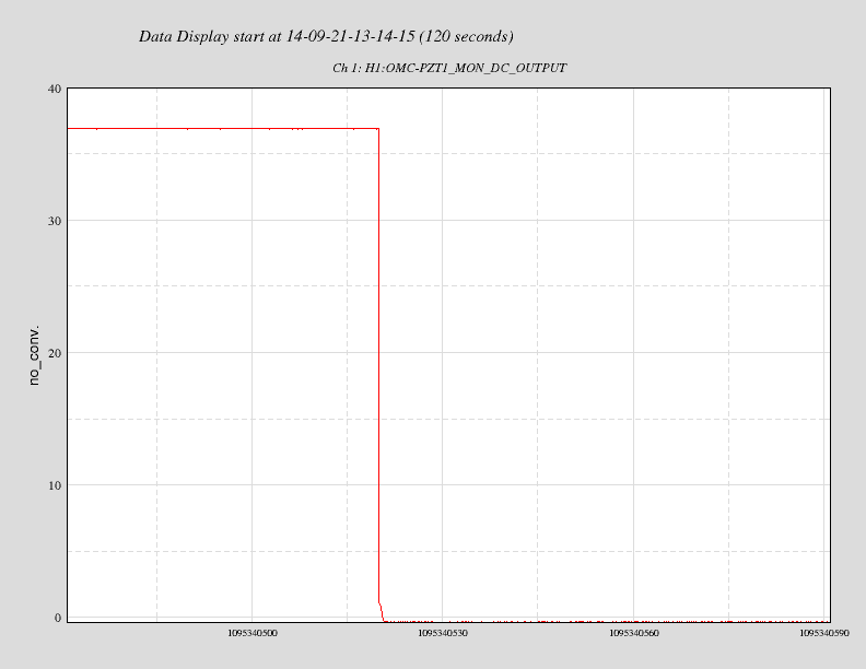
One more thing: when I came in on Sunday the PZT HV supply was tripped. According to the EPICS readbacks this happened around 6:15am local time on Sunday (see attached). Not sure why this HV supply would trip by itself, but if you try to move the PZT and nothing happens, go check the HV...
Images attached to this report
Non-image files attached to this report

Comments related to this report
There was a minor power bump at LHO around 0615 that would have caused this trip. Not all systems were bothered by this power anomaly. Only one of the UPS units bothered to report it so it must have been right around a threshold.