Sudarshan, Peter, Keita, Gabriele
Checking the power on the diodes
According to the electornic schematics, the ISS second loop transimpedance board has two parts:
- the transimpedance has large bandwitdh and a conversion factor of 1600 V/A
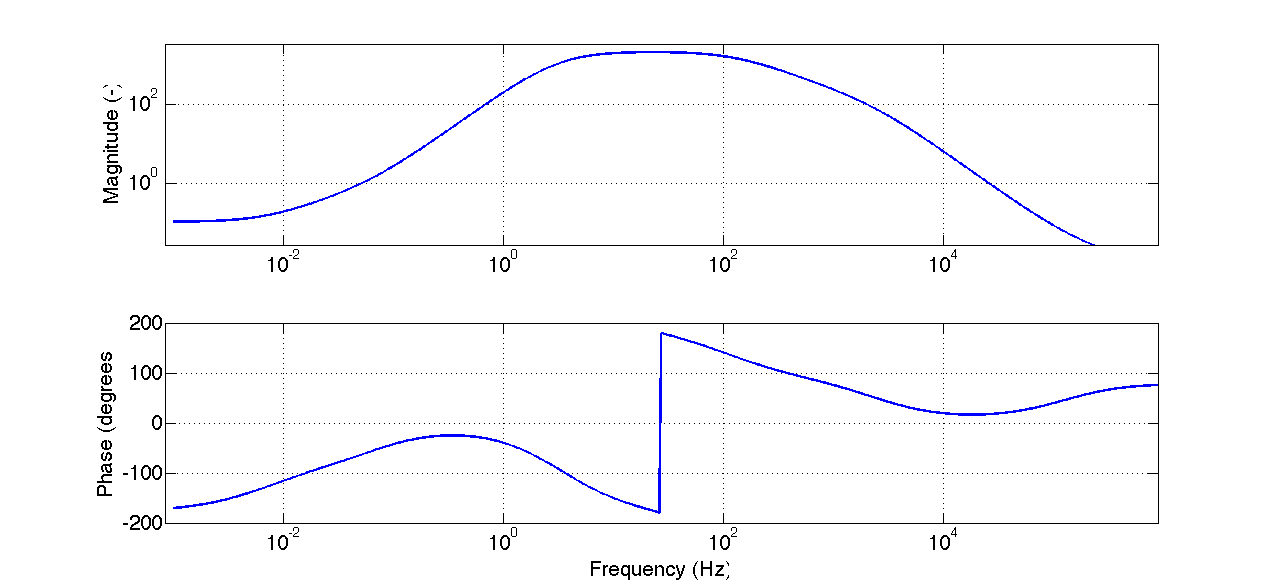
- the following part is a "whitening" filter with a DC gain of -20 dB, inceasing after a corner at aout 10 mHz, flattenig at about +66 dB at 10 Hz, and then low passed above 200 Hz. See the first attachment for a Bode plot
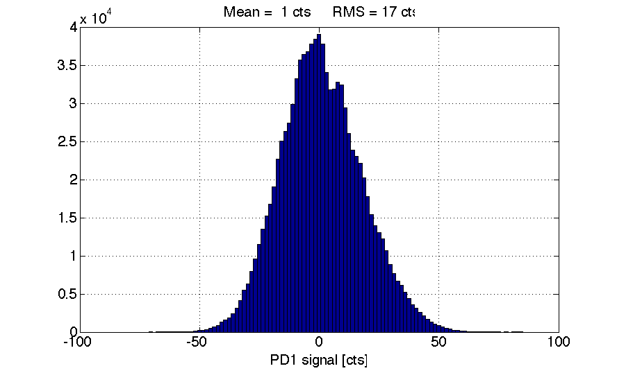
With the present input power of 10 W, we should have something like 10 mW into the array, which means 1.25 mW per photodiodes, corresponding to about 1.0 mA of photocurrent. After the transimpedance we should get 1.6 V and 160 mV at the output of the board. This should corresponds to about 260 counts. However, we see that the RMS of the photodiode signals is about 17 counts and dominated by high frequency, while the mean value is ver close to zero, about 1 count (see second attachment, one minutes of data). It seems that we're not getting all the power we should.
We also checked in the electronics lab, with one spare board, that sending 1 mA at the input gives the expected signal levels both after the transimpedance stage and at the output. We also checked that adding a long cable at the input doesn't have any effect on the result.
Calibration of PD signals
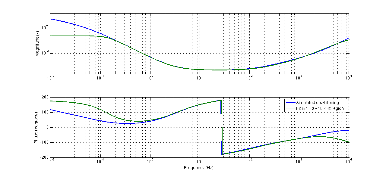
Using the nominal whitening transfer function and transimpedance, we computed the calibration filters t be implemented in the PD filter banks. We don't want to have any 10 mHz pole, so we actaully fitted the whitening ransfer function between 1 Hz and few kHz, see third attachment (blue nominal TF, green implemented TF). Therefore, the PD_OUT signals are calibrated in mA only between about 1 Hz and 5 kHz. Below and above the signals are uncalibrated. This is expecially true for the DC level, which is not correct. Later on, once we'll have solved the missing power problem, we'll implement a calibration in units of RIN.
The result are shown in the forth attachment. The high frequency content of the 1-4 diodes (one board) is clearly different from the 5-8 diodes (the other board). We still don't know if this is due toa really different signal or to a different response of the board. Again, once we'll have solved the missing power problem, we'll see if this difference is still there.
Picomotor game
Right now we are quite sure that the beam is not properly hitting the PDs:
- the power level is very low
- the signal level on the eight diodes is quite different
- there is a large coupling of angular motions to power
So we wanted to move the beam using the two mirrors with picomotors. Of them, we were sure of the cabling of only the older one, which is the one closer to the ISS box and after the telescope. To make the story brief, we moved the picomotor by few 10000 steps in horizontal, bua saw no difference either in the QPD or PD signals. We could however see some "shaking" of the signals. Instead, moving in the vertical direction produced no result. So we're not sure if the picomotor is actually working. As for the second picomotor, we could not understand if it's cabled or not.
More investigations on the pico story tomorrow...