Peter K, Gabriele
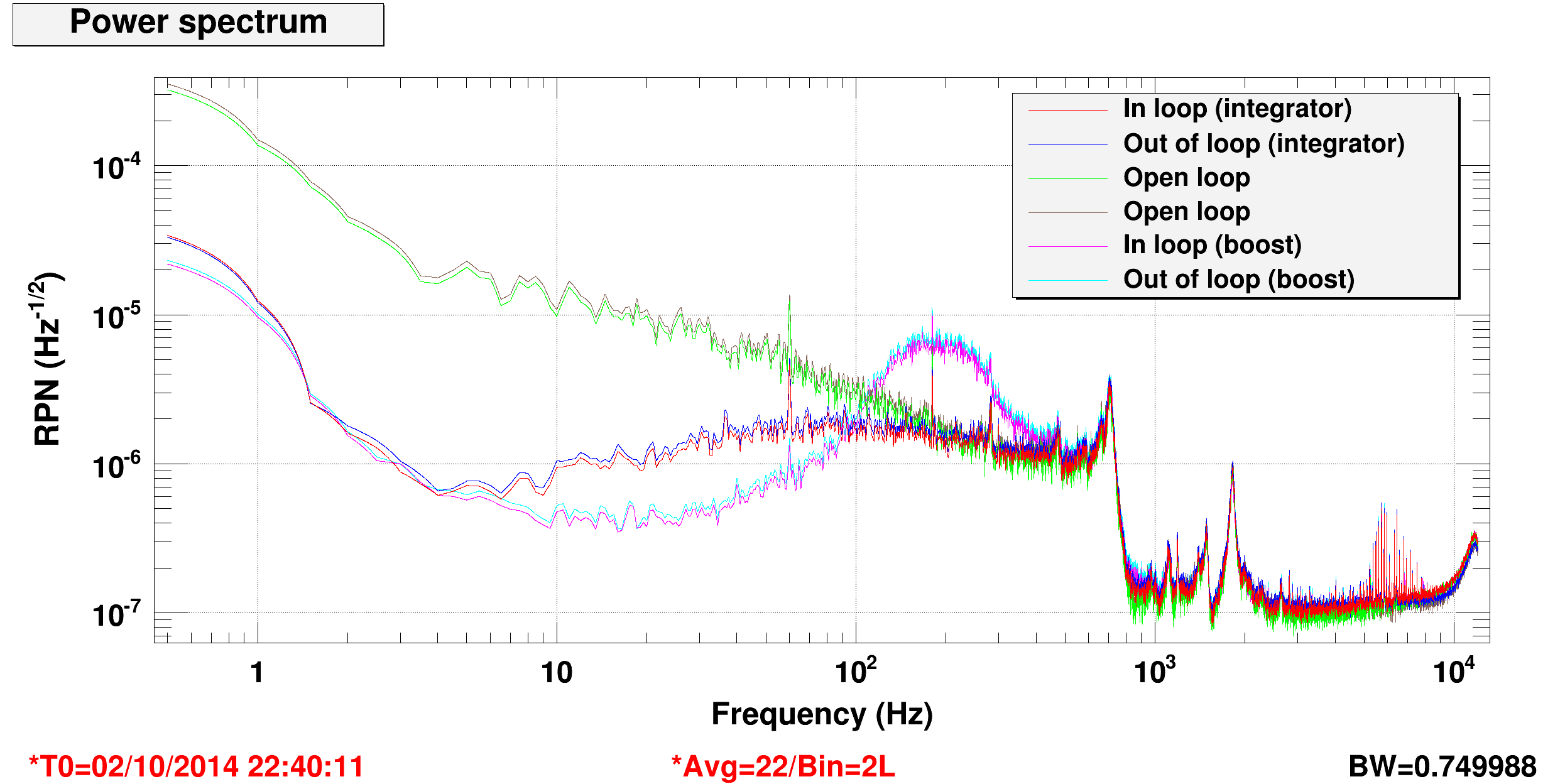
In brief, we finally managed to close the ISS second loop. The attached plot compares the intensity noise measured on the second loop photodiodes in different configurations: second loop open (green and maroon), loop closed withe the additional integrator (red and blue), loop closed with the additional boost (cyan and magenta).
Clearly, the boost doesn't do a very good job. With the integrator on, we get a loop bandwidth of the order of 200 Hz, and a gain at 10 Hz of something like 10-15. We don't have enough gain to cope with our present large power noise after the IMC.
Procedure to engage the second ISS loop
- All switches should be low (H1:PSL-ISS_SECONDLOOP_CLOSED, H1:PSL-ISS_SECONDLOOP_SERVO_ON, H1:PSL-ISS_SECONDLOOP_BOOST_ON, H1:PSL-ISS_SECONDLOOP_INT_ON)
- Move the second loop gain to the minimum (H1:PSL-ISS_SECONDLOOP_GAIN to 0)
- Switch on the second loop (H1:PSL-ISS_SECONDLOOP_SERVO_ON to high)
- Adjust the reference input H1:PSL-ISS_SECONDLOOP_REF_SIGNAL_ANA to move the output of the second loop as close as possible to zero (check H1:PSL-ISS_SECONDLOOP_SIGNAL_OUTMON)
- Switch on the additive path in the ISS inner loop (H1:PSL-ISS_SECONDLOOP_CLOSED to high)
- Increase the gain to maximum (H1:PSL-ISS_SECONDLOOP_GAIN to 40)
- Engage the integrator (H1:PSL-ISS_SECONDLOOP_INT_ON to high)
Some details
The input signals to the second loop servo board (the two sums of photodiodes) were not behaving correclty: they appeared to be choppen at the zero level, meaning that only the positive (or negative) part of the signal was present. We traced dow the problem to the OP27 which is used in the output stage of the transimpedance box. This OP27 was used to create a single ended monitoring of the box output, which was sent to the front panel and not used. For some reason we don't understand yet, this opamp was creating the problem. We removed it from the two boards and the sum output is now good.
We also modified the ISS model to wire in the two additional switches ADD_GAIN and ADD_PD_58_SUM. We plan to modify the additional gain module to get an additional factor of ten in the gain.