Peter K, Gabriele
Loop performance, excess sensing noise
As reported yesterday, the second loop servo didn't have enough gain, so this morning we modified one switchable stage of the board to include a x10 gain. Unfortunately, that stage is an inverting one, so we can't really switch it on and off with the ISS second loop closed. This stage is controlled by H1:PSL-ISS_SECONDLOOP_ADD_GAIN.
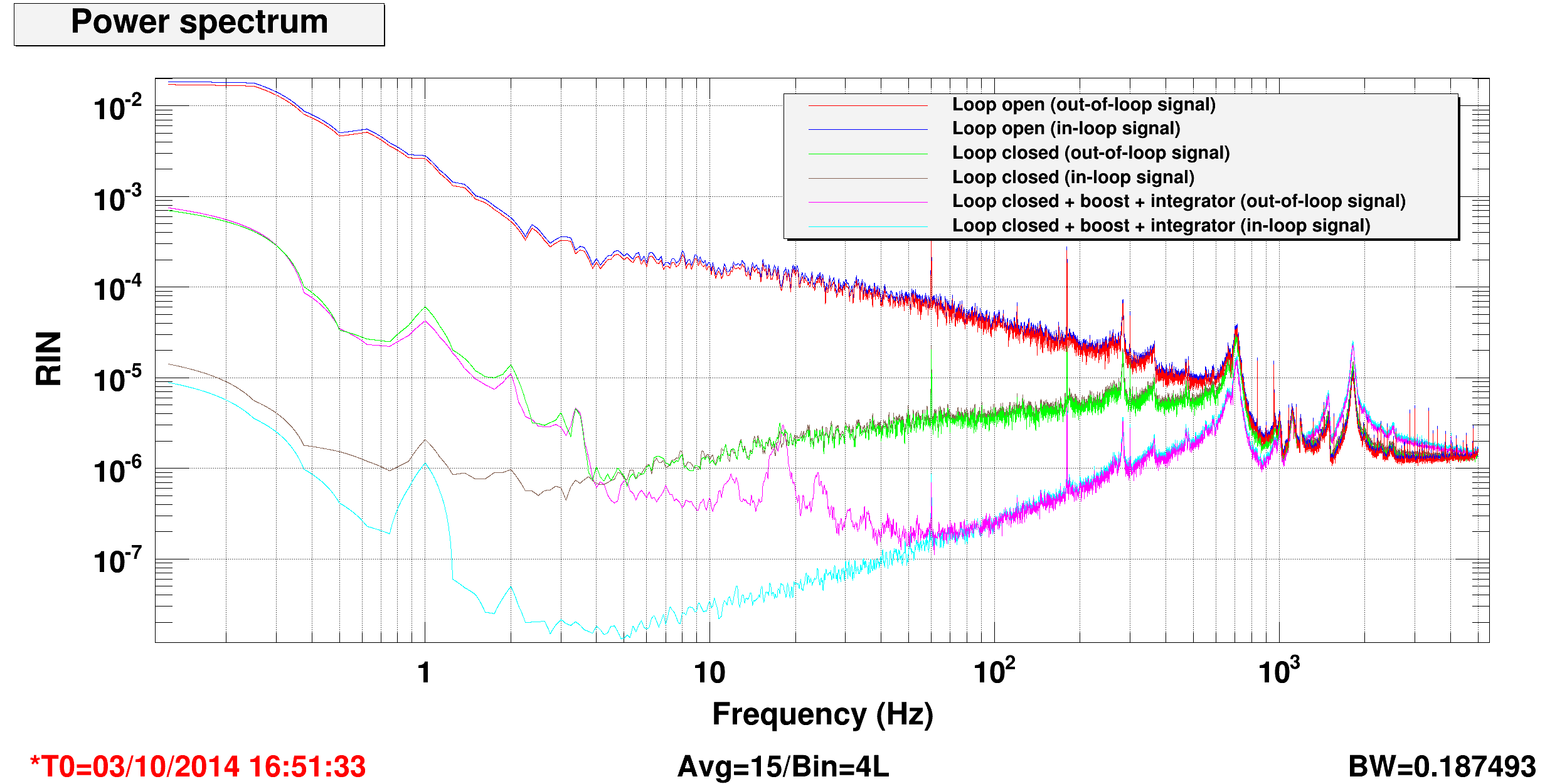
Using everything we have in the board (maximum gain at +40dB, x10 stage, integrator and boost) we could engage the second loop and get the performance shown in the first attached plot. The red and blue traces are the in-loop and out-of-loop signals, calibrated in RIN, when the second loop is open. The green and maroon traces are again the same signals, with the loop engaged with maximum gain. The cyan and magenta traces correspond to the integrator and boost switched on. We're getting a bandwith of about 1 kHz.
We can see that the out-of-loop signal shows an excess of noise with respect to the in-loop signal, up to about 60 Hz. The out-of-loop RIN is about 1e-6 at 10 Hz and 2e-7 at 60-70 Hz. We can conclude that our ISS second loop photodiodes are limited by sensing noise of some kind at this level.
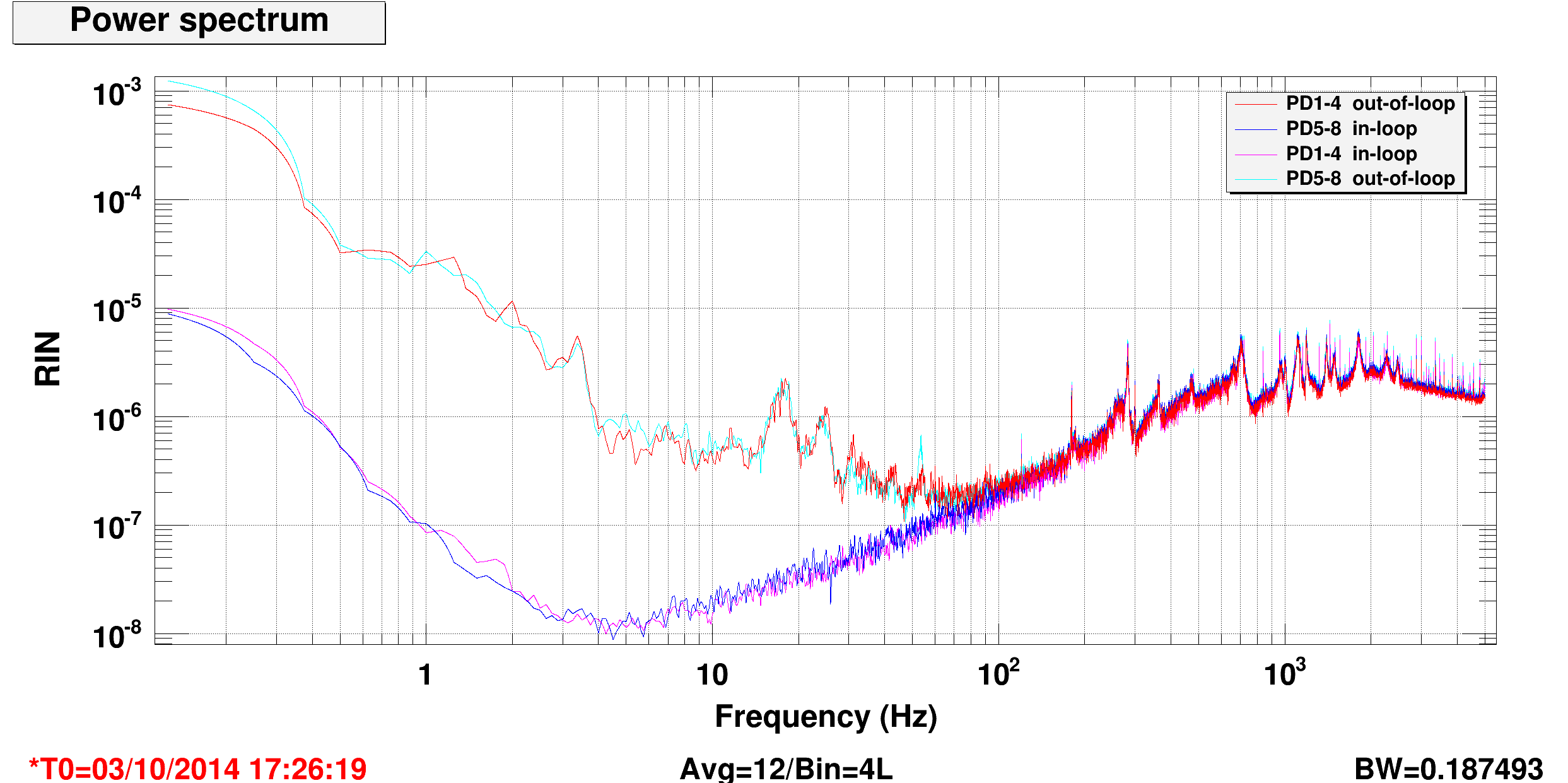
The second plot shows a comparison of the error signals (sum of photodiodes 1-4 and sum of photodiodes 5-8) with one or the other in loop. The performance is very similar in the two cases, so the amouint of excess sensing noise is about the same in both sets of sensors.
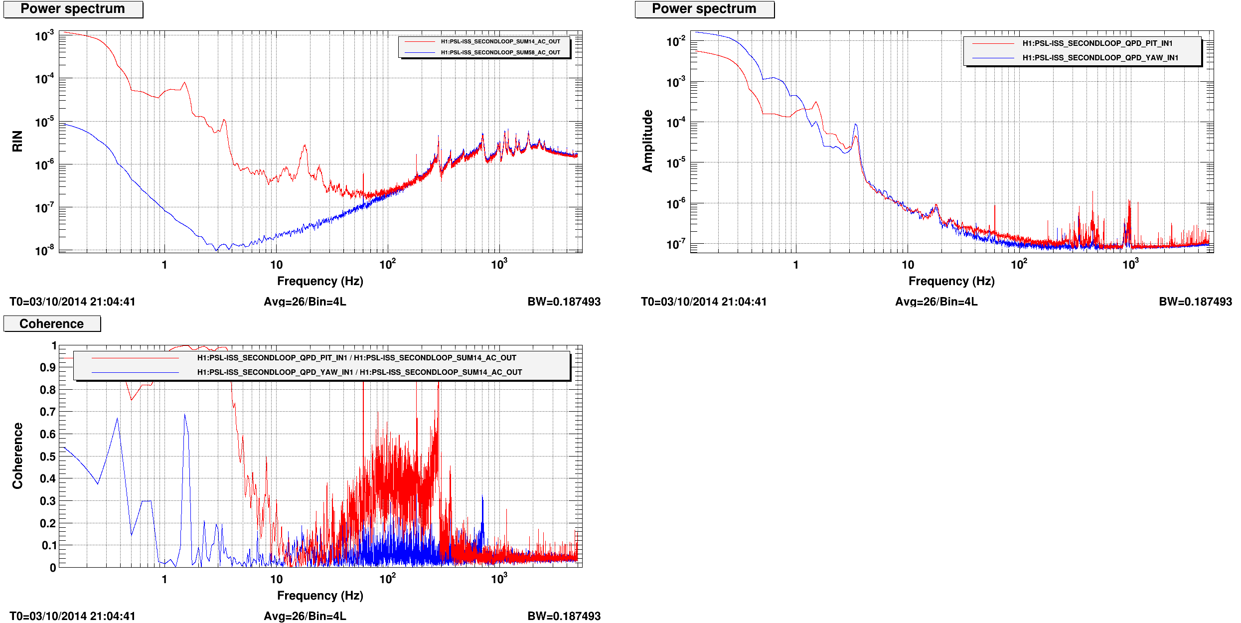
The last plot shows that there is some coherence between the out-of-loop signal and the ISS QPDs. This is true at least at low frequency, below 10 Hz. The QPD signals show a structure at ~18 Hz which is very similar to the one visible in the out-of-loop signal, altough there is no coherence. It might be due to a highly non stationary coupling, but we're not sure of that. So it is likely that at least some of the excess sensing noise is due to beam jitter to intensity noise coupling at the ISS array. to imrpove this, we should try to move the beam using the picomotors and looking at the out-of-loop signal noise in the 10-60 Hz region.
How to switch on the ISS second loop
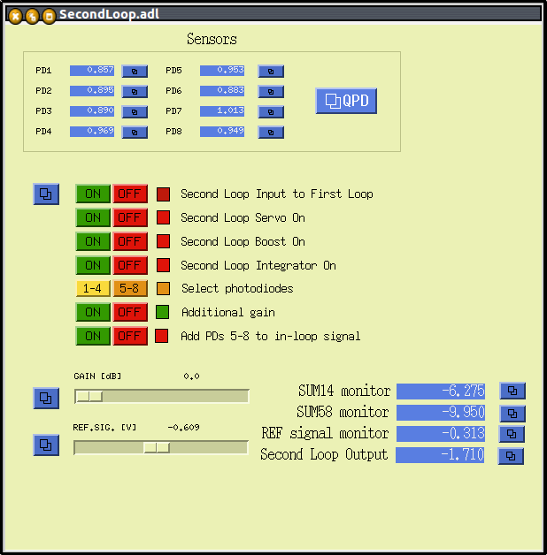
The medm screen of the second loop is wrong, in the sense that the buttons are connected to the wrong switches. I created a new screen for the second loop, which for the moment is living in /ligo/home/controls/gabriele/SecondLoop.adl. Once finalized, we should move it to the right place.
- Switch off the connection between second loop and first loop (H1:PSL-ISS_SECONDLOOP_CLOSED to low level)
- Ensure that the additional gain path is on (H1:PSL-ISS_SECONDLOOP_ADD_GAIN to high)
- Move the loop gain to 0 dB (H1:PSL-ISS_SECONDLOOP_GAIN)
- Engage the second loop servo (H1:PSL-ISS_SECONDLOOP_SERVO_ON to high) and tune the reference level (H1:PSL-ISS_SECONDLOOP_REF_SIGNAL_ANA) to move the sencond loop output signal (H1:PSL-ISS_SECONDLOOP_SIGNAL_OUTMON) as close as possible to zero. You won't be able to get zero, just ensure that it is oscillating with a rough zero mean. You might need to tune the reference signal at the mV level.
- Switch on the connection between second loop and first loop (H1:PSL-ISS_SECONDLOOP_CLOSED to high level). Some times this kicks the first loop out of lock, but usually it is able to recover withtin few seconds. Watch the diffracted power, since any small error in the reference signal for the second loop will have a large impact. You might have to retune the reference signal
- Increase the gain to the maximum (+40 dB) and engage boost (H1:PSL-ISS_SECONDLOOP_BOOST_ON) and integrator (H1:PSL-ISS_SECONDLOOP_INT_ON)
To do
- automate the whole switch on procedure, including th zeroing of the second loop output tuning the reference signal
- when the IMC drops lock, we should automatically switch off the ISS second loop
- try to move the beam into the array using the picomotors, to minimize the out-of-loop noise