Latest news from the OMC:
==== Beam stabilization at the dark port ====
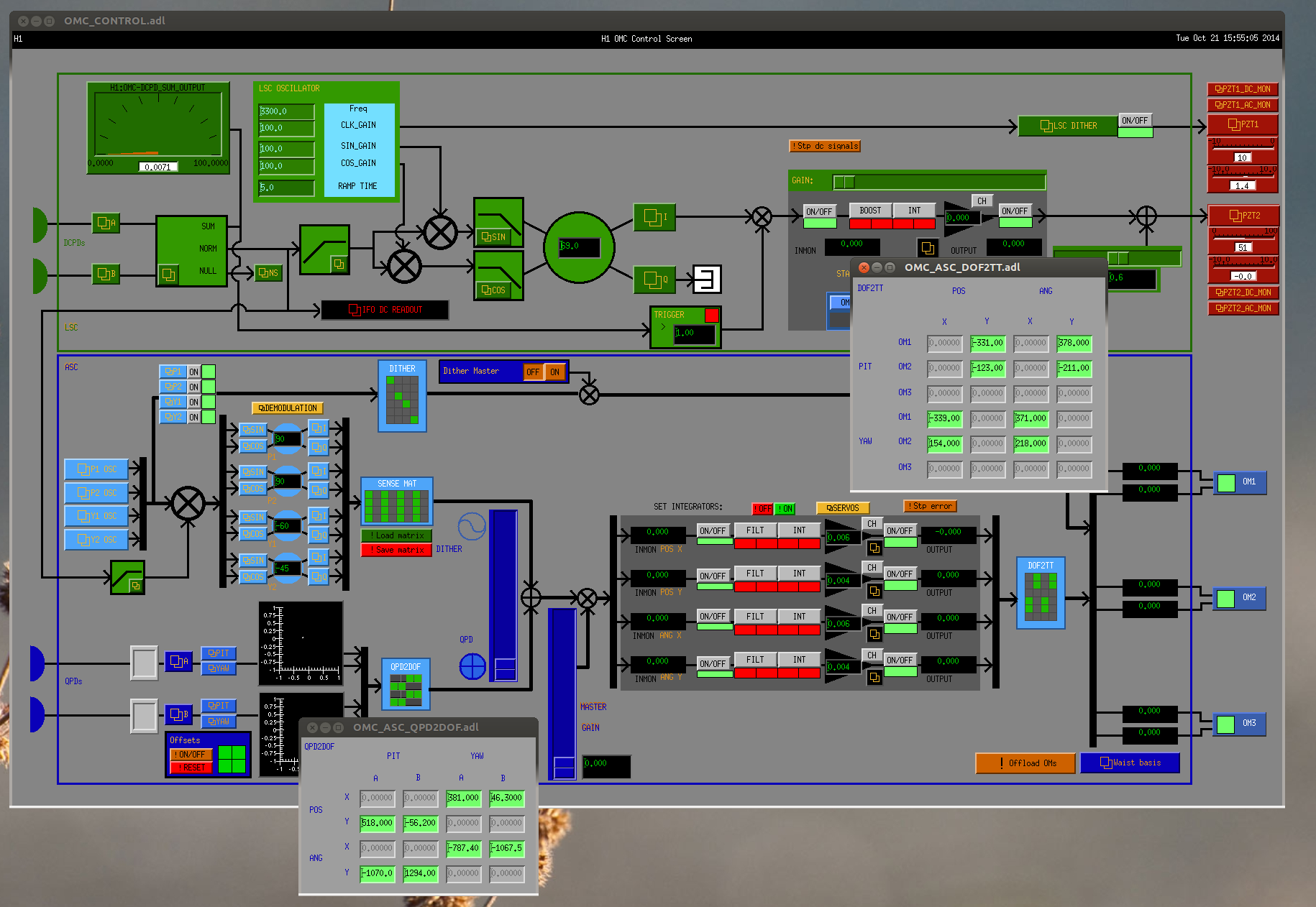
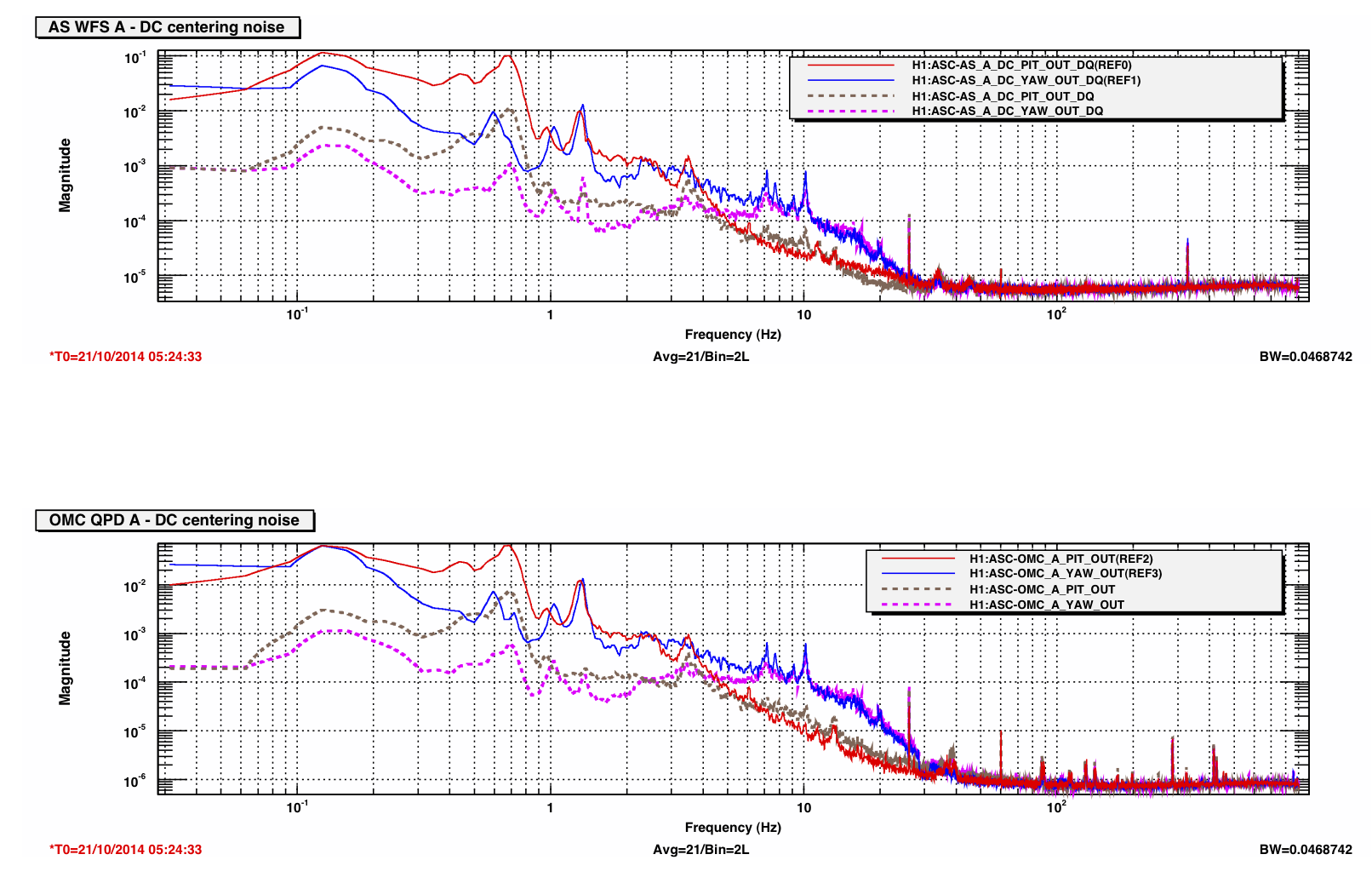
To keep the beam centered on the both the AS WFS and the OMC, I recalculated the actuation matrix for the OMC alignment loops, following Koji's calculations in T1400585. Instead of using OM1 and OM3 for the alignment control, now we use OM1 and OM2, so that all of the control is upstream of the WFS. This works very well; the low-frequency beam motion on the WFS is suppressed by 10x or more. In the first plot attached the solid lines (references) are without the OMC alignment loops engaged, the dashed curves are with the OMC QPD servo on. It doesn't look as though ASC-DC loops from the WFS --> OMs are necessary, but this may change when the dark port is dominated by higher-order modes (all this work was in a single-bounce configuration). In principle any motion of the OMC suspension relative to the WFS will not be suppressed, from the point of view of the WFS, since the OMC QPDs are on the OMC breadboard, and the WFS are fixed to the table.
Anyways if you want to keep the beam centered on the AS WFS, you can set the OMC guardian to the 'ASC_QPD_ON' state. The guardian control should be robust in the event of locklosses (if there's no light on the QPDs it will run the OMC down script and wait for the beam to return). Note that if cavities are moving through fringes this will screw everything up, so maybe it makes sense to have the OMC guardian managed by the DRMI when ASC loops are being tuned.
==== Offset locking state for the OMC (also some gain swapping) ====
To measure the length noise in the OMC I added another state to the OMC guardian, OFFSET_LOCK, that moves the lock halfway off-resonance. The procedure follows what Zach outlined at LLO. I found some gotchas that had to be solved: the high-pass filter on the input to the LSC demod needs to be turned off, and the DCPD normalization has a *lower* saturation limit at 0.1 that will totally ruin the DCPD NORM signal for small transmitted power on the DCPDs. (The overall dc gain in the DCPD A and B filter banks is -122.4dB, so we hit the lower limit pretty easily.) To keep us from hitting the lower rail, I moved a gain factor of 1000 from the DCPD SUM filter bank to the DCPDs themselves, this keeps the output of DCPD_NORM_FILTER above the lower saturation limit. The NORM channel is used for the OMC LSC and the SUM (which previously had the 1000x gain, now moved upstream) is sent to the IFO LSC, but the change is common to both DCPDs, and the overall SUM signal hasn't changed, so this adjustment should be transparent downstream of the DCPD conditioning.
==== OMC stability over several hours ====
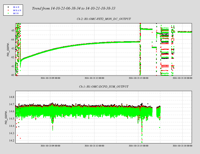
Last night the OMC was locked on a single bounce from ITMY for about eight hours. The PZT control drifted by 2V, slowly approaching an equilibrium state, and there was no change in the transmitted power. (There was a small earthquake just after 0900 UTC that caused some noise in the DCPD SUM.) It relocked a couple of times on its own in the morning. This is with the QPD servo enabled, not the dither, so the alignment stability is somewhat better than what we'll use for the full IFO.
A 2V change in the PZT drive corresponds to a 28nm change in the cavity length (from T1000276). The DCPD SUM channel should be calibrated for mA (I think), and for a single-bounce beam with 10W input to the IMC there should be about 19mW at the dark port. To do: calculate the expected change in cavity length and the time constant to see if this 2V shift in drive is what we expect from thermal expansion of the breadboard.
==== OMC LSC demod phase ====
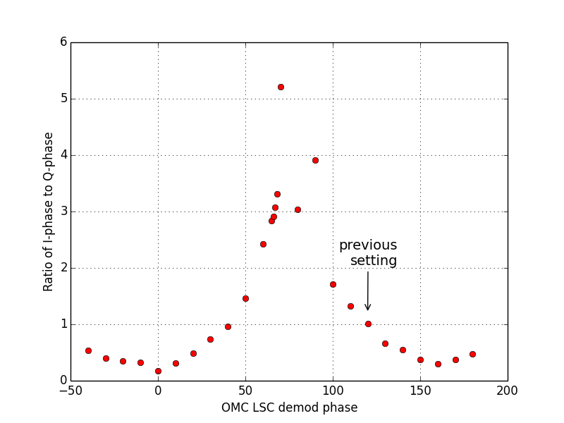
I repeated Nic's measurement of the demodulation phase for the OMC LSC dither loop. With the OMC LSC loop open, I moved the PZT slightly off resonance, turned on a 100Hz excitation in PZT1, and adjusted the demod phase so that the ratio of the I-phase / Q-phase was maximized. I found a phase of 70deg was optimal; this is quite a bit off from Nic's observation of 120deg. I'm not sure how different our methods were, or whether a drift of ~50deg over ~2 months is something we should expect. We'll keep an eye on this phase and see if it keeps changing.
As an alternative to the OMC QPD servo, I set up the ASC DC3 loop for centering the beam on the AS WFS. The ASC input and output matrices are now set to use AS_A,B --> DC3,4 --> OM1,2. Both loops have the same filters (in the DC centering filter banks), and the gains are generally the same (although I found the AS_A yaw loop, DC3_Y, was unstable and needed to be 3x lower than the others). By eye, the current gain settings provide about the same stabilization as the OMC QPD servo, so the UGFs are probably around 5Hz. Previously we had been using DC4 to center the beam on AS_A, this worked ok but using two loops is quite a bit more stable. The filters that are enabled are FM1,2,3 and 5, although I have left the integrator (FM2) off for now. Probably the thing to do is cycle the integrator on lockloss in the guardian. Or clear the history.
I edited the guardian scripts (ENGAGE_CORNER_WFS_CENTERING in the ISC_GEN_STATES module) to turn on the correct matrix elements and filters. Also I added the DC3 loops to the CORNER_WFS_DC_centering_servos_OK function. These names are getting a little rococo.