Alexa, Kiwamu
We did three items tonight:
-
We tried the good IM4 YAW bias that Keita found out today (see alog 14567) by steering PR3/PR2 and IM4.
- => failed and got confused. We set these biases back to the usual values.
-
We made a comparison of the DRMI spectra with and without the BS yaw oplev damping loop
- => found that the BS yaw oplev loop was contaminating the length signals and also increasing the chance of the SRC hopping.
-
We checked tolerance in the angle of the SRC-related optics by intentionally introducing offset.
- => BS was the most sensitive optic which let the DRMI enter the 01 mode instability with misalignment of about 0.2 urad.
(IM4 angle)
We aimed for -8000 counts in IM4 yaw bias which is the value that Keita found out to be good from the point of view of cavity loss. We did this by steering PR3 while keep closing the IM4+PR2 ASC loops for the input pointing with respect to the arm cavity. This resulted in yaw biases of -162.70 and 762.99 urad for PR3 and PR2 respectively. The original biases were -177.30 and 629.26 urad respectively. Since this resulted in misalignment in the POP beam, we had to steer some optics on ISCT1 to recover the light on the POP diodes.
However this resulted in a weaker light at the POP path, due to a clipping somewhere in chambers. The POP beam did not like a Gaussian beam any more and looked enlongated vertically. See the attached movie for getting idea of how it looked like. The movie shows the POP beam in front of the top periscope mirror on ISCT1. The power build-up in POPAIR_RF18 was smaller by more than a factor of 5. I think this is a clipping in somewhere in the POP path at the outside of the PR cavity because we could lock the DRMI without changing the LSC gains -- the optical gains stayed almost the same.
We decided to go back to the nominal angles and set PR2 and PR3 back to the usual values. We realigned the optics on ISCT1 again.
One thing we got confused is that, after restoring PR2 and PR3 back to the usual values, the IM4 YAW bias did not have to move at all in order to get a good pointing toward the X arm. Maybe we simply do not understand what we are doing.
(DRMI length signals are contaminated by BS YAW oplev damping)
During the IM4 anlge study, we came up with a hypothesis that somehow the BS oplev damping loops were kicking the BS and let the SRC hop to some other modes. So we made a comparison with and without the oplev loops running. We found the following two facts:
- BS YAW oplev damping loop was contaminatong the length signals at around 10 Hz
- Engaging the yaw damping loop seemed to increase the number of hopping.
The plot below is the DRMI spectra with and without the YAW oplev damping loop. Note that the PIT loop was untouched and left on all the time during this measurement:
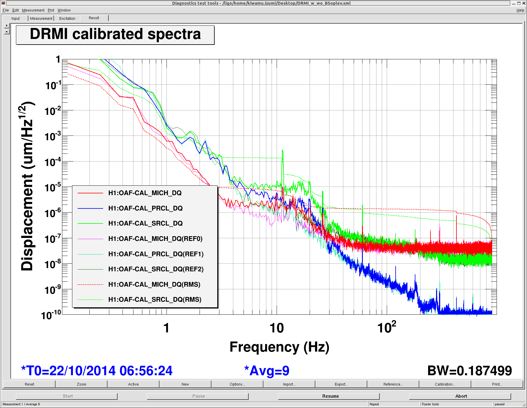
The ones in vivid colors (red, blue and green) are the spectra with the oplev loop running. The other curves are the ones without the oplev loop running. It is obvious that the noise between 4 and 20 Hz increased by some amount. In particular, the noise level in SRCL increased by roughly an order of magnitude. This contaminatin was repeatable.
(Tolerance in optics' angle)
We introduced intentional misalignment in the SRC optics in order to see how big misalignment they can tolerate. The below are the measured tolerance that gave us the 01-mode instability:
- BS = 0.2 urad
- ITMX = 0.5 urad
- SR3 = 0.5 urad
- SR2 = 4 urad
- SRM = 16 urad
All the numbers shown here is for the yaw direction. We did not measure it in pitch.
