Aidan. Alastair. Greg.
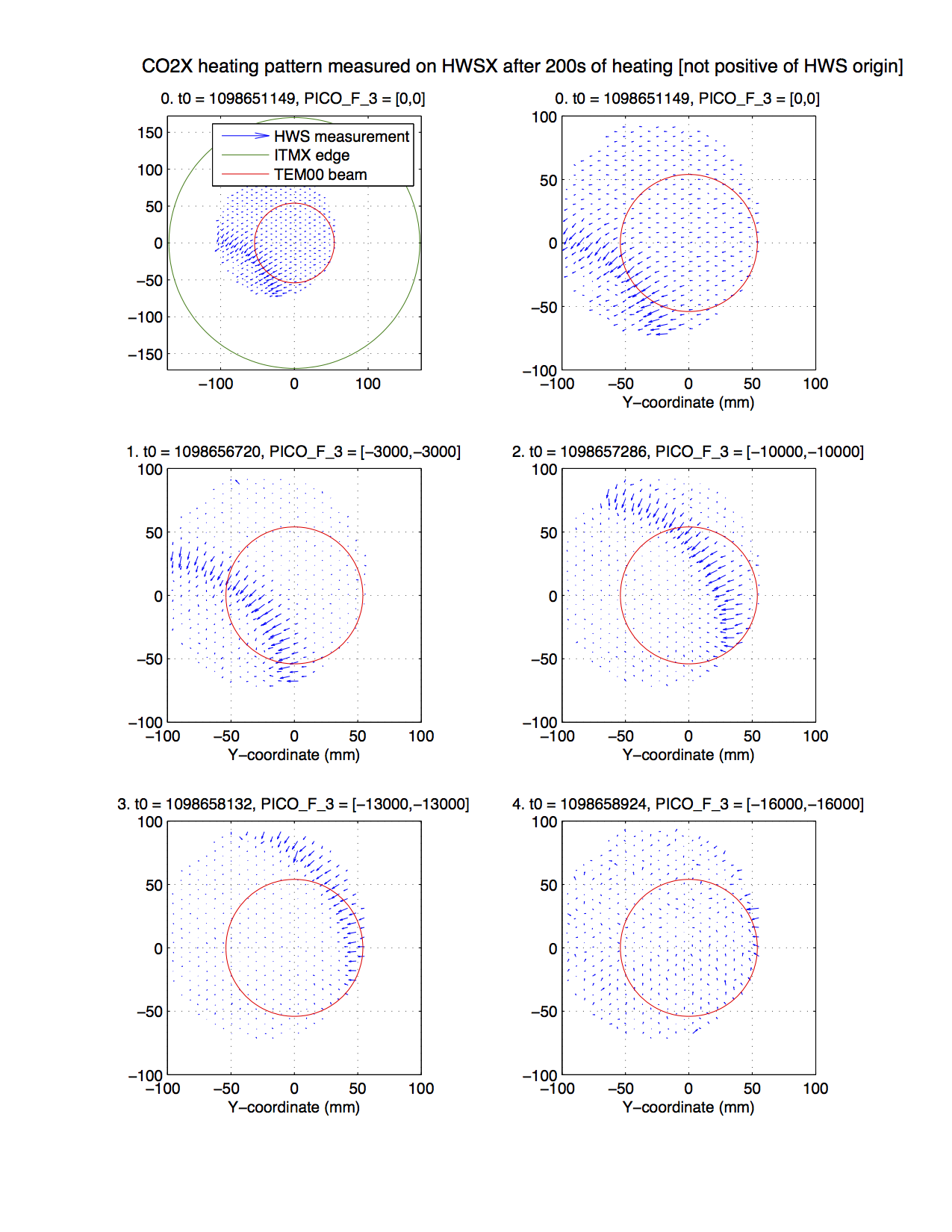
We started heating ITMX with the central heating beam while running the HWSX sensor. We observed the gradient field of the HWS sensor (created from the difference between before and after 1W of heat applied for 100-200s). The sharp edge of the heating pattern was clearly visible in the gradient field.
We iteratively adjusted the upper periscope mirror on TCS CO2X (PICO_F_3) to adjust the alignment to ITMX. As a roughly calibration we measured 42 mm of motion for 7000 counts applied to the picomotors, or with the signs included:
Displacement on ITMX = [-6, -6] micrometers per count on PICO_F_3
I'm not 100% confident that the calibration of the center of the optic is correct. However, the HWS gradient field displayed here is adjusted to the coordinates of the test mass using this morning's RH measurement.
Also, note that we're measuring the position of the CO2 laser beam using the transient thermal lens which provides a strong signal at the edge of the heating beam during the initial stages of heating. The measurements below do not represent the steady-state thermal lens which will look significantly different.
However, the bottom line is that the CO2X central heating beam that was not correctly aligned to the center of the test mass is not much closer to being aligned. We will continue to fine tune this tomorrow.
The plot below shows the iterative alignment of the CO2 heating beam. The first and second panels are the original alignment. The second panel is zoomed in around the HWS measurement. The green circle represents the edge of the test mass. The red circle represents the diameter of the TEM00 mode of the IFO. The blue arrows are the HWS gradient field. The strong arc visible in the bottom left corner is the edge of the CO2 heating beam thermal lens. The PICO motor counts for the upper periscope mirror are shown in the titles for the plots.