(Corey, Filiberto, Hugh, Jim, Mitch, Vincent)
**** This covers Testing & Installation of Cables for BSC8 which covered much of this week. ****
Swapping Cables & Laying Them Out For Final Configuration
Other than the Capacitive Position Sensors, cabling for the BSC8-ISI had been Class-B. This week we swapped out these cables for Class-A cables, and positioned them on the ISI in a "final configuration". Photographed cable layouts, and posted in ResourceSpace, here. Below are the serial numbers and locations for all of the cables we installed this week.
Cable Serial Numbers
| Drawing # (D11001__) | S/N (S110____) | LOCATION |
| _48 | _4051 | Corner1_Stage1_Horiz Actuator Extension |
| _48 | _4050 | Corner1_Stage1_Vert Actuator Extension |
| _48 | _4057 | Corner1_Stage2_Horiz Actuator Extension |
| _48 | _4058 | Corner1_Stage2_Vert Actuator Extension |
| _50 | _5188 | Corner1_Stage1_Horiz Actuator |
| _50 | _5187 | Corner1_Stage1_Vert Actuator |
| _51 | _4085 | Corner1_Stage2_Horiz Actuator |
| _51 | _4084 | Corner1_Stage2_Vert Actuator |
| _52 | _5193 | Corner1_Trillium |
| _53 | _4556 | Corner1_GS13 Extension |
| _53 | _4557 | Corner1_L4C Extension |
| _54 | _4256 | Corner1_L4C |
| _55 | _4120 | Corner1_GS13 |
| _48 | _4056 | Corner2_Stage1_Horiz Actuator Extension |
| _48 | _4049 | Corner2_Stage1_Vert Actuator Extension |
| _48 | _4047 | Corner2_Stage2_Horiz Actuator Extension |
| _48 | _4048 | Corner2_Stage2_Vert Actuator Extension |
| _50 | _5189 | Corner2_Stage1_Horiz Actuator |
| _50 | _5186 | Corner2_Stage1_Vert Actuator |
| _51 | _4086 | Corner2_Stage2_Horiz Actuator |
| _51 | _4094 | Corner2_Stage2_Vert Actuator |
| _52 | _5192 | Corner2_Trillium |
| _53 | _4560 | Corner2_GS13 Extension |
| _53 | _4561 | Corner2_L4C Extension |
| _54 | _4257 | Corner2_L4C |
| _55 | _4122 | Corner2_GS13 |
| _48 | _4055 | Corner3_Stage1_Horiz Actuator Extension |
| _48 | _4054 | Corner3_Stage1_Vert Actuator Extension |
| _48 | _4053 | Corner3_Stage2_Horiz Actuator Extension |
| _48 | _4052 | Corner3_Stage2_Vert Actuator Extension |
| _50 | _5191 | Corner3_Stage1_Horiz Actuator |
| _50 | _5190 | Corner3_Stage1_Vert Actuator |
| _51 | _4082 | Corner3_Stage2_Horiz Actuator |
| _51 | _4083 | Corner3_Stage2_Vert Actuator |
| _52 | _5194 | Corner3_Trillium |
| _53 | _4558 | Corner3_GS13 Extension |
| _53 | _4559 | Corner3_L4C Extension |
| _54 | _4258 | Corner3_L4C |
| _55 | _4121 | Corner3_GS13 |
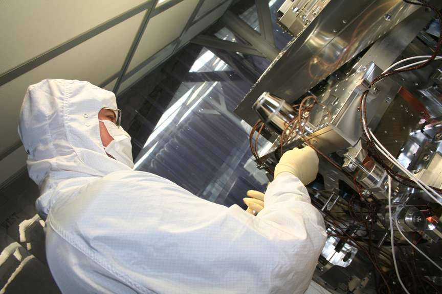
SUS Viton Cable Clamps Installed
Swapped out Peek cable clamps with newer Viton Cabl Clamps for the SUS cabling strung on the side (at Corner3) of the ISI (we did NOT address any clamps on the Optical Table. (photo of Jim installing a clamp is attached)
Testing Seismometer Cables
Before connecting cables to the Interface Feedthrus and Powering ON the seismometers, we used our Emulator box to test out the cables for the L4C's and GS13's. (We were not able to test out the Trillium Cables; we tried the STS2 Emulator, but this did not work for us.)
Balancing Stage 2 & Capacitive Position Sensor (CPS) Issues
On Wed night we made an attempt at checking/balancing the ISI because the SUS group wanted to run measurements on a floating ISI. We were surprised at how much Stage2 was off. It took a while, but we were able to get all the Vert CPS under 0.5V.
After this, we locked up Stage2, and unlocked Stage1 to begin balancing, but then we noticed we had a railed (+13V) V3 CPS. In all liklihood, we are going to have to swap this CPS and board out (we checked it and its cabling several times to no avail).
Change to Cabling Table Above
After routing cables last week, we tested Actuator cables and it was noticed (2) Actuators were wired up wrong (Corner3's Horiz & Vert Fine Actuators were basically switched). The cables were then switched.
On Friday afternoon, I did one more check of all of our cables to confirm everything matched the documentation, and sure enough I saw that the (2) actuators we switched were physically cabled to the wrong actuators!
This morning, we checked the cabling here, and the problem was traced to the Position Sensors (what we use to look at what the Actuators do). The Horiz & Vert Fine Capacitive Position Sensors (CPS's) were the culprits (a Horiz cable was connected to a Vertical Sensor, and vice versa). These CPS's were switched to a correct configuration, and the Actuators were also switched.....all this switching occurred at the Interface Feedthru.
So, to be thorough, here is the correct cabling layout for the Fine Actuators at Corner 3 (:
| Drawing # (D11001__) | S/N (S110____) | LOCATION |
| _48 | _4052 | Corner3_Stage2_Horiz Actuator Extension |
| _48 | _4053 | Corner3_Stage2_Vert Actuator Extension |
| _51 | _4083 | Corner3_Stage2_Horiz Actuator Extension |
| _51 | _4082 | Corner3_Stage2_Vert Actuator Extension |