evan.hall@LIGO.ORG - posted 14:35, Monday 01 December 2014 - last comment - 16:10, Monday 01 December 2014(15362)
DRMI1f characterization (no arms)
Lisa, Kiwamu, Alexa, Sheila, Elli, Evan
Sensing matrix adjustment
The matrix element for REFLAIR_A_RF9I → SRCL has been adjusted from −8.8 to −3.75. The procedure was as follows:
- We drove a 30 ct, 131.7 Hz sine wave into PR2.
- We monitored the spectrum of LSC-SRCL_IN1, and then adjusted the matrix element until the line at 131.7 was minimized. The improvement was about a factor of 100 in ASD.
Open-loop transfer functions
After the sensing matrix adjustments, we measured the OLTFs of PRCL, MICH, and SRCL. Plots and data are attached.
Note that the PSL power may have been slightly low here because the rotation stage didn’t restore the nominal power completely. So the optical gains during nominal PSL power may be a factor of 10 % higher or so.
Modehopping test
We found that a BS misalignment of 0.2–0.3 μrad in either pitch or yaw is sufficient to induce hopping of the SRC mode from TEM00 to TEM10/TEM01. We did this as follows:
- With DRMI1f locked, we let the WFSs bring POPAIR_B_RF18_I and ASAIR_B_RF19_I to maximum power. Then we turned off the WFSs loops (but kept the good alignment).
-
With a 2 s ramp on the BS alignment sliders, we moved the BS alignment in 0.1 ct steps until we saw hopping on the ASAIR camera.
For what it’s worth, the hopping appears “cleaner” and more bistable. We no longer get a wobbly, pacman-looking junk mode; the mode is definitively either 00 or 10/10, and it stays that way if we don’t touch the BS slider.
Non-image files attached to this report


Comments related to this report
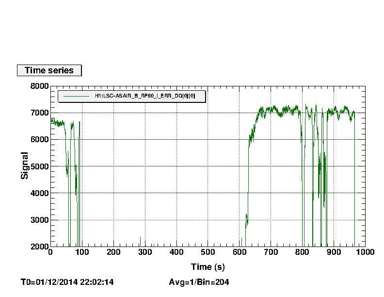
Below are plots with the SRC sideband power vs BS misalignment. The "hopped" region corresponds to ~0.3 urad misalignment wrt to the "aligned" state. The power drop is about 30%. This is pretty similar to what has been observed before using the TCS to match the ITMs thermal lenses.
Images attached to this comment