Dan, Koji
This is a followup to Koji's post that described our OMC work on Sunday. (Here I give details of the noise investigations; the measurement of the OMC actuator noise was described by Koji yesterday.)
The summary is that the excess ~1kHz noise in the OMC length error signal is not consistent with intensity or alignment fluctuations, and isn't being amplified by a resonance on the OMC breadboard. This agrees with Zach's investigations from L1. The peaks are consistent with cavity length noise that is driven by acoustic noise coupling into the chamber via the ISI, but our measurements aren't conclusive. We will have to see if the noise appears in DARM -- at L1 this doesn't appear to happen.
1) Intensity noise suppression by ISS first loop.
First we investigated the stability and noise suppression of the ISS first loop. We found we could reliably close the first loop once the input offset had been tuned, but oscillations would develop when the integrator was turned on.
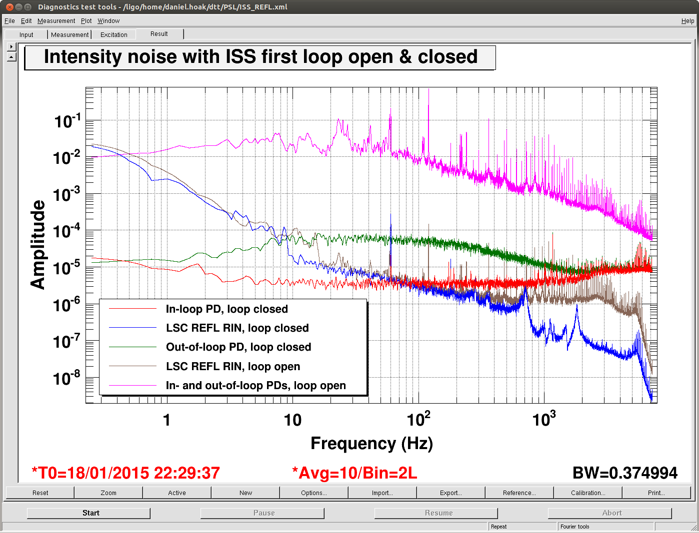
The first plot is intended as a qualitative reference of the performance of the ISS first loop. The intensity noise measured by the LSC REFL photodiode is improved above 300Hz with the first loop on, but the noise below 300Hz is unchanged, and there are peaks (at 700Hz, etc) that are not suppressed. Is this noise coming from the IMC?
(We had to use the REFL PD to measure the intensity noise after the IMC because the beam going to the ISS second loop PDs is misaligned.)
2) 1kHz peaks in OMC noise - intensity noise, alignment jitter, or OMC length noise?
Next we locked the OMC on a half-fringe and studied the noise. If the peaks at 1kHz are due to intensity noise (maybe due to a bad ISS), the coupling should increase as we move the OMC lock from the half-fringe to the full fringe. If the noise is due to beam jitter, we can change the coupling by moving the alignment into the OMC. If the peaks are due to real cavity length noise it should couple more strongly at the half-fringe lock.
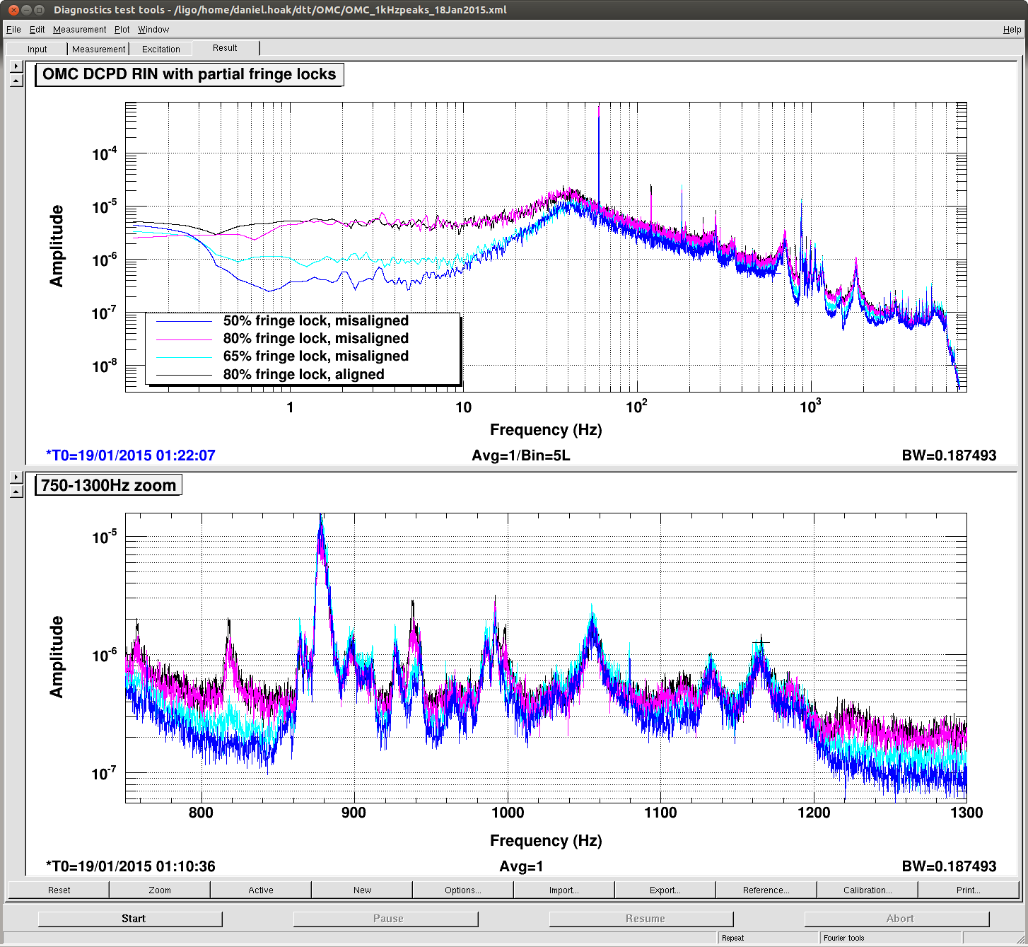
The second plot tells the story -- there was no change in the peaks when we misaligned the cavity (compare purple and black), which seems to rule out beam jitter. There was some change in broadband noise as we moved the locking point up the fringe (compare blue, to cyan, to purple); this indicates that we were limited by intensity noise. In particular the peak at 817Hz in the lower plot is consistent with an intensity noise explanation. But, the other peaks were mostly unchanged as we detuned the cavity (although the 877Hz peaks seemed to be slightly worse at the 50% fringe). This appears to rule out intensity noise, but it's not really consistent with cavity length noise, either. So, we're baffled.
(Regarding beam jitter: we had tuned the alignment into the OMC by using offsets in the QPD loops to minimize the linear coupling between excitations of the tip-tilts to the OMC TRANS spectrum. Turning the offsets on reduced the height of alignment dither lines by 10x. So, we should have seem *something*, if the peaks were due to beam jitter.)
For reference, the frequencies of the largest peaks are the following: 817, 877, 937, 991, 1055, 1132, 1165 Hz. The location of the DTT file is at the top of the figure.
3) Comparison between PDH error signal and OMC TRANS.
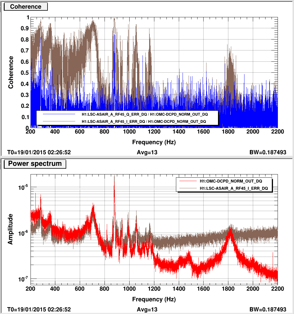
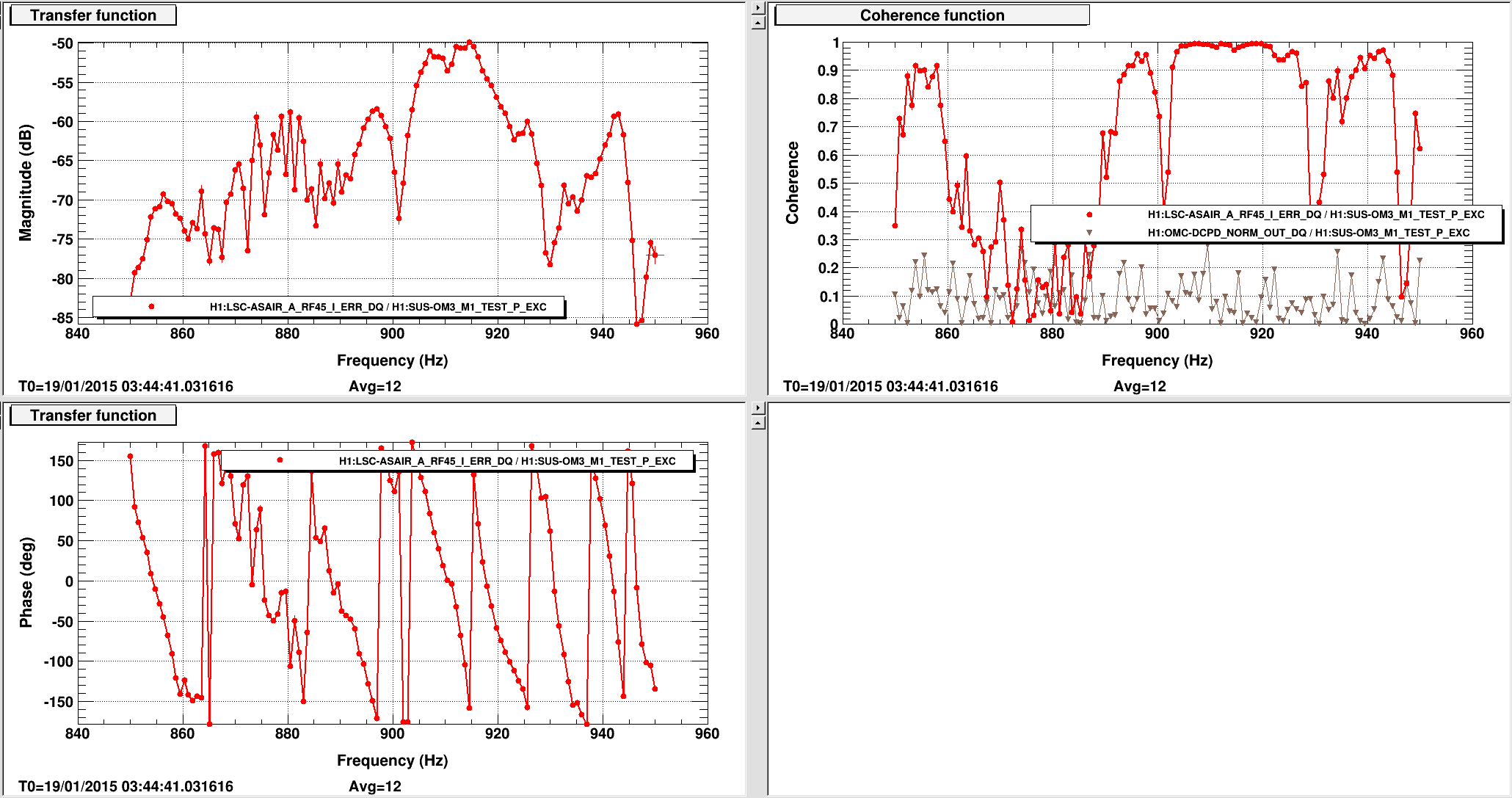
Next we steered the OMC REFL beam onto ASAIR to use the PDH error signal as an out-of-loop sensor for the cavity length. Here, the cavity was locked at 80% of a fringe, to move the PDH error signal into the linear region. The third plot compares the PDH error signal (out-of-loop) to the OMC TRANS noise. (We rotated the ASAIR_A phase to maximize the signal in the I_phase - see coherence in top panel.) In the lower panel I've used a calibration factor to overlay the two curves. The peaks around 1kHz appear in both signals, which also rules out intensity noise as a source. The peak at 817Hz only shows up in OMC TRANS, not the PDH signal --> still consistent with an intensity noise source.
4) Transfer functions from OMC SUS and tip-tilt SUS to PDH error signal
The only hypothesis that remains is real length noise in the cavity. This idea is supported by Robert's measurements of the ISI, which showed that noise from outside the chamber can be transmitted through the ISI due to resonances at ~1kHz.
We thought that the ISI resonances could be lining up with resonances in the OMC breadboard. Koji had measured a breadboard resonance around 1kHz in bench tests, although the boundary conditions of the suspension points were different from the in-vacuum suspension.
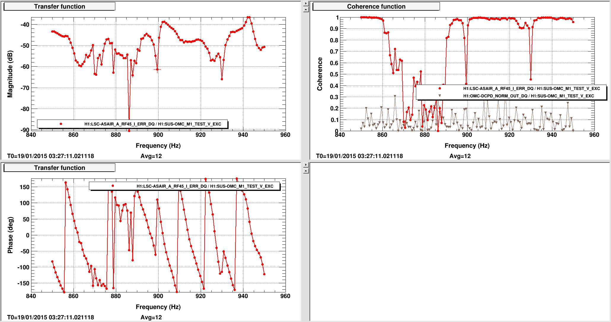
So we tried to excite the modes using the SUS. The fourth plot is a swept-sine transfer function of the OMCS vertical mode to the PDH error signal. There's no coherence at the frequencies of the noise peaks; we believe this rules out the OMC breadboard resonances as the source of the peaks. But at other frequencies our excitation was coherent with the length error signal, and the transfer function is pretty flat; the implication is that the OMC breadboard has a flat response, approximately, to excitations in the SUS, which means that noise from the ISI might couple into the cavity length. Not good.
We also tried to measure the beam jitter coupling in the same band, using a pitch excitation on OM3. This is the fifth plot, and the story is the same - coherence in some bands, but not at the peaks in the noise spectrum. Also not good. (It wasn't clear to us why beam jitter noise was coupling into the PDH error signal. The cavity was locked using the length dither with a 30Hz UGF, so it's hard to imagine jitter at 900Hz being impressed upon the cavity length via the dither servo.)
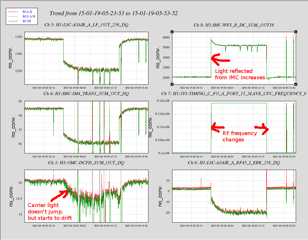
5) Encore noise investigation: IMC DOF4 error point and sideband detuning
Right at the end of the day I was setting up a measurement of the IMC cavity pole. With the OMC locked, we noticed that changing the frequency of the 9 and 45 MHz sidebands slightly off the IMC resonance would cause the OMC TRANS signal to drift down. Eventually we realized that moving the sidebands by 20kHz changed the reflected power from the IMC, which moved the error point for the DOF4 loop and slowly misaligned the IMC. See the sixth plot. This isn't really surprising, but it was pretty confusing for a few minutes. (The many dropouts in the plot are due to the ISS becoming unstable - these show up in the DC power signals but not in the ASAIR_A_RF45_I_ERR.)