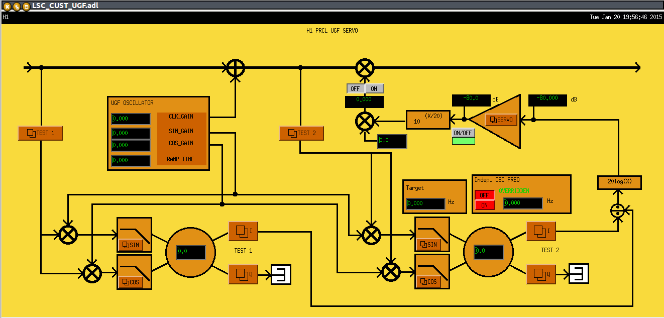
Math puzzle: What's wrong with this UGF Servo?
its installed for use in the OMC and LSC at the moment, and could be used in the ASC if we find we want to hold the UGFs constant during TCS tuning.
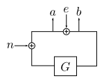
We want to measure . The algebra tells us that
,
.
When the excitation is sufficiently large that the noise is negligible, we get .
and
are complex quantities, and the real and imaginary parts are the I and Q outputs of the demods, or
,
.
In the version of the UGF servo that Rana posted, the phases would be chosen such that the imaginary (Q) outputs are zero, thus
.
This is OK as long as G only ever changes in magnitude, otherwise .
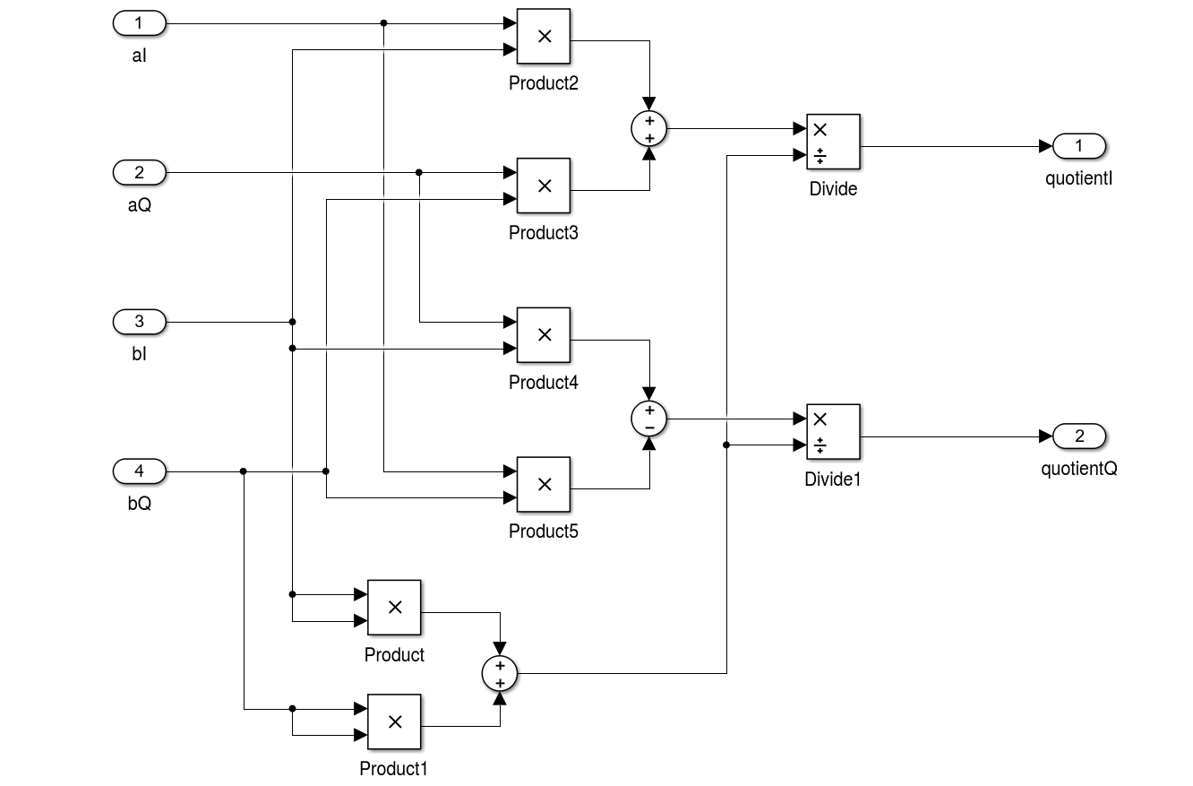
To get the correct measurement in the case of a changing phase, one must do the following:
This is implemented in the attached simulink model.

(First of all I don't know the answer yet)
I believe G only changes the gain most of the case.
The problem was
a/e = G/(1-G) and b/e = 1/(1-G) change their phase as you change the gain of G.
We usually don't care the phase of G, but only care the magnitude of G as the phase of G is fixed.
Therefore what we need is to take the ratio of the magnitude of a and b
|a| = |G|/|1-G|, |b| = 1/|1-G|
|a|/|b| = |G|, where |a| = sqrt(aI2+aQ2) and |b| = sqrt(bI2+bQ2)
(Ed: I'm suggesting to take SQRT(I^2+Q^2) to eliminate the frequently-omitted-effort of adjusting the demod phase correctly.)
Meh, I say it's overkill. As Nic mentions, this works just fine if the UGF phase is not changing, so long as you set the demod phase correctly. As Koji mentions, the UGF phase should not be expected to change that much. It is already a second-order effect, so what is there now should be fine, unless we really want to accommodate wild loop phase fluctuations at the UGF. Is there a reason that's ever something we want?