Summary:
Green straight shot beam size on ITMX is a factor of 0.87 of nominal (i.e. too small) while ITMY a factor of 1.2 too large.
The beam radius ratio is (X/Y)=0.72, which makes the ITMX baffle PD output current to be a factor of 2 larger than that of Y when you hit these PDs using a straight shot beam.
There used to be a factor of 2 to 2.5 unexplained difference between the photocurrent in ITMX and ITMY baffle diodes during initial green alignment, but the beam size explains a factor of 2, so the remaining factor is about 1.2 or so, which I don't care for now.
Background:
This is one of those health check type stuff. Baffle PDs could be used for scattering measurement but the health of some of those PDs were in question.
One of the suspicions came from the fact that, when looking at green straight shot beam during full initial alignment, PD current from X arm baffle is much larger than Y arm. A part of it comes from the laser power (there's about a factor of 2 or so difference) but the baffle PD current is a factor of 4 to 5-ish different, so there always was a factor of 2 to 2.5 unexplained.
Details:
I first used dither align script to point the TMS beam to PD1 and then PD4 of the ITM baffle. Since the horizontal distance between PD1 and PD4 is 11.3", the script allows us to calibrate TMS alignment slider.
Immediately after the script finished, I pointed the beam to PD4 center, move TMS in YAW in one direction by more than the beam radius, and ran another script to move TMS in YAW, wait and measure PD4 current.
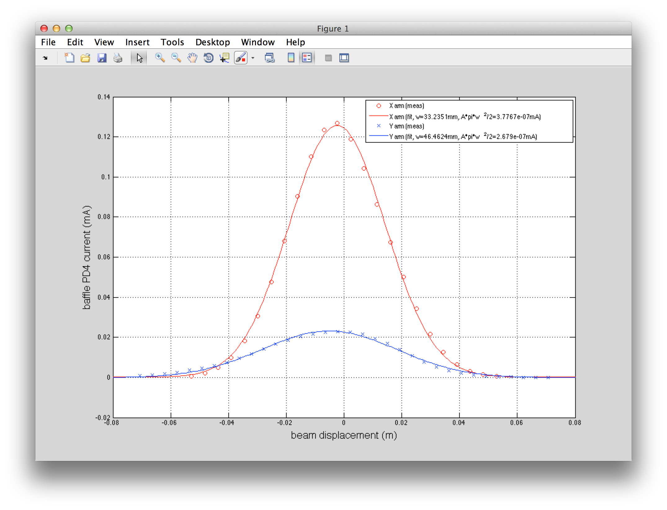
Attached is the YAW scan data (circles and crosses) as well as the fit to Gaussian profile assuming the same radius in PIT and YAW:
current = ofst+ A * 2/pi/w^2 * exp(-2*(X-X0)^2/w^2)
where w is the beam radius and A is an overall factor.
| beam radius [m] | A [mA m^2] | QPD_SUM | |
| IX PD4 | 0.033 (0.038 nominal) | 3.8E-7 | 46180 |
| IY PD4 | 0.046 (0.038 nominal) | 2.7E-7 | 26124 |
| X/Y | 0.715 | 1.4 | 1.77 |
The last column in the above table shows QPDA_SUM+QPDB_SUM. If everything makes sense, and if the beam was at the same height as the PD center during the scan, QPD_SUM ratio should agree with A ratio, but apparently it doesn't at 20%-ish level. This is good enough because the suspicion was that there was something grossly wrong about the baffle PDs.
BTW we can do the same thing for IR beam, scanning MMT3, to assess the IR matching to the arms if we want to (or better yet, do the spiral scan to see both PIT and YAW).