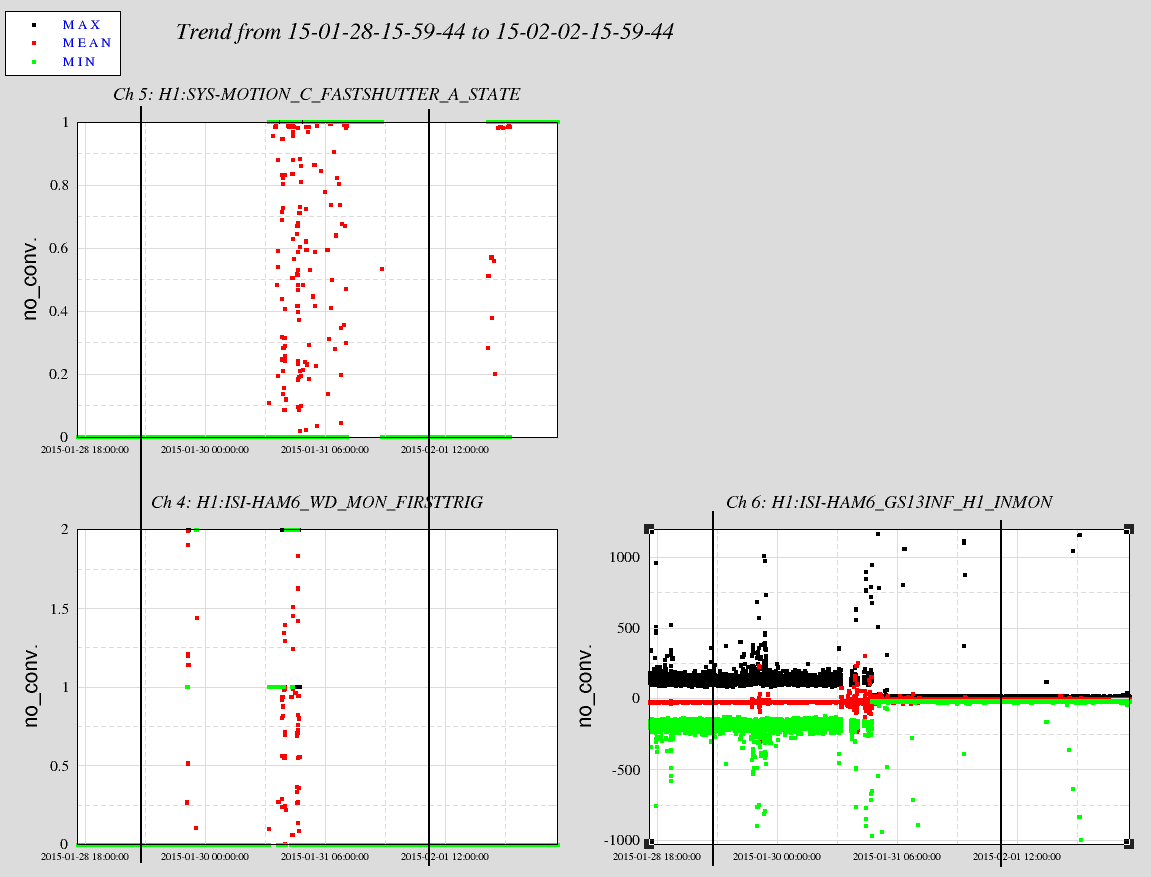
The first attachment is a time series of the HAM6 Watchdog, the Fastshutter State, and a GS-13 trace on HAM6. The switch to low Gain is clear on this last trace. This is a 5 day trend and the ~20 minutes needed to get the below .005Hz BW data is comfortably unmolested by the ISI or the fastshutter--the start times of the Spectra calculations begin at the vertical black lines. As for ISI trips and shutter fires--there were none.
The High Gain Spectra period begins at 0800utc on 29 Jan, the Low Gain Spectra begins at 0800utc 1 Feb.
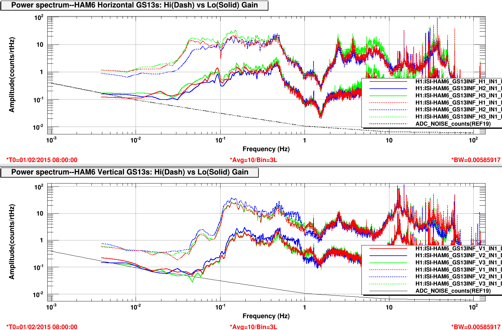
The second attached graph has Horizontal GS13s on HAM6 in High and Low Gain on the upper plot. The Verticals are in the lower plot. High Gain Spectra is Dashed, Low Gain traces are Solid. Also shown is our ADC noise in counts.
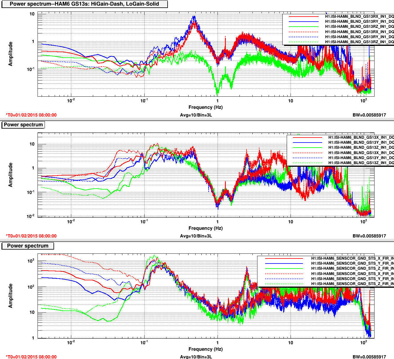
One caveat is that the ground motion is different at the two times. The third attachment shows the Cartesian DOFs for the HAM6 GS-13s in the upper two plots and the ground noise in the bottom plot. We've had a ground motion decrease in the microseism frequencies and below during the low gain period. You can see the Low Gain Spectra are at the ADC level below 50mHz. And the 10x signal reduction expected is more like 5x below these frequencies. If this conclusion passes mustard, we'll have to revisit the GS13 triggering delays/levels.
DTT template is /ligo/svncommon/SeiSVN/seismic/Common/MatlabTools/HAM6_GS13_GainNoiseTest.xml
J. Kissel, H. Radkins

Which GS13 gain/whitening configurations are the "right" gain configurations?
How many times have we asked this?
Hugh is trying to settle this once-and-for-all with quantifiable results like the above entry, but I relay the history and current problems with the GS13 gain / whitening switching below.

The GS13 Interface Board (D1002706), used for both HAM and BSC ISI GS13s (in D1000067 and D1002432, respectively), has two *independent* switches: one for an analog whitening filter (switching between a flat gain of 1, or a zero:pole filter of 10:50 [Hz] -- a gain of 1 at low-frequency, 5 at high frequency), and one for analog gain (switching between a flat gain of). Thus, there are four possible gain/whitening states for this interface board. See attached visual aide.

These two states are compensated for digitally in FMs 4 and 5 of the GS13INF banks, by the difference between the two states (the overall gain of 2 is folded into the calibration filter). FM4 is the switchable gain compensation, FM5 is the switchable compensating de-whitening filter. The front-end code for the HAMs and BSCs is set up that these digital banks control the analog switching.
- When FM4 is ON, the gain switch is HI (or a binary output of 1), so the analog gain is 2, and FM4 compensates the gain of 10 difference.
- When FM4 is OFF, the gain switch is LO (or a binary output of 0), so the analog gain is 20.
- When FM5 is ON, the analog whitening is LO (or a binary output of 0), so there is no whitening, and FM5 compensates the z:p = 50:10 difference.
- When FM5 is OFF, the analog whitening is HI (or a binary output of 1), so the whitening is engaged.

A long time ago, Brian had performed a design study (see G1000412) that had suggested (on pg 24-25) that
"Low Gain Mode [is] good enough to get close to requirements at all [frequencies] above 300 [mHz], tilt[-horizontal] coupling [from vertical GS13 noise turning into RX & RY, which causes X & Y].
[In] High Gain Mode, ADC noise is at least 2x below the sensor noise at all frequencies."
where he defines
"Low-gain is DC gain of 2, with a zero at 10 [Hz], pole at 50 [Hz]"
and
"High-gain is fixed gain of 12 (input stage of 6)."
Clearly the later statement is now out-of-date with respected to the current revision of D1002706, but the intention is clear --
HI Gain = analog gain ON, analog whitening OFF (FM4 OFF, FM5 ON)
LO Gain = analog gain OFF, analog whitening ON (FM4 ON, FM5 OFF)
Indeed -- that a "Gain of 10" and "No Whitening" is the "nominal" configuration is now written directly surrounding the circuit in the schematic D1002706.
Why? Because
- having *no* whitening or additional gain (i.e. FM4 and FM5 ON, or an overall interface response of a flat gain of 2), you'll likely be buried in the ADC noise floor at all relevant frequencies, and
- having *both* whitening and additional gain (i.e. FM4 and FM5 OFF, or an overall interface response of low-frequency gain of 20 and high-frequency response of 100, with a z:p pair at 10:50 [Hz]) will likely saturate the ADC.

Further, this was solidified in a SEI team summit at the March 2011 meeting, notes were taken (see T1200373) that say the following:
"
FM4 - Switchable Readout Gain:
	- Gain of 10 (7) [113] (cancels fixed gain in FM1)
	- FM4 is ON when analog gain is OFF
	- FM4 is ON in "low gain" mode (analog x10 gain is OFF)
	- FM4 is hooked to analog gain via BIO, such that when FM4 is turned OFF, the analog gain is turned ON
	- Choose for analog switch to happen at zero crossing (a bit you can flag in the foton .txt file)
FM5 - Switchable Whitening (for GS13s only):
	- Filter matches analog whitening (cancels fixed dewhitening in FM1)
	- FM5 is ON when analog whitening is OFF
	- FM5 is OFF in "low gain" mode (analog whitening is ON)
	- FM5 is hooked to analog whitening via BIO, such that when FM5 is turned ON, the analog whitening is turned OFF
	- Choose for analog switch to happen at zero crossing (a bit you can flag in the foton .txt file)
"

Seems clear, right? Great.

Here's the problem:

(1) The front end does not restrict the user from the ADC-noise-swamped state, lets call it "ultra-lo gain mode," of FM4 and FM5 ON (additional analog gain and whitening OFF) or the ADC saturating state, let's call is "ultra-high gain mode," of FM4 and FM5 ON (additional gain and whitening ON).

(2) The python command script used to switch between the modes is
${userapps}/isi/common/scripts/sensor_hilo
and IT ONLY SWITCHES FM4. This (and the name "hi gain" and "low gain") has confused users who only use this command script into thinking that the difference between the two relevant states is *only* the x10 gain and FM4.

This had resulted in chaos and confusion during LHO's period of revolving commissioners, and ingrained a long-standing, almost superstitious, confusion about what "low gain" and "high gain" states mean.

Thankfully, I think after 15 discussions on SEI calls, 20 individual-to-individual email chains, and some LLO spy sessions via remote log-in over the past few years, Jim and Hugh have settled on what Brian thought was right answer for GS13s back in 2010:
- All* HAMs are in high-gain mode (with FM4 OFF and FM5 ON, i.e. additional analog gain of 10 and no whitening.)
- All* BSCs are in high-gain mode ("")
Why do I have asterisks next to ALL in both cases that continue to add to the confusion?
Because of blasts from lock-acquisition / lock-loss.

From experience with DRMI lock-acquisition, LLO has found that ISI BS ST2 GS13s saturate regularly if in (nominal, not ultra) hi-gain mode. If the GS13s are in the (nominal, not ultra) low gain configuration, they don't saturate. As such, for the ISI BS only, we use the nominal lo-gain mode.

For experience with the Fast Shutter closing and opening on HAM6, LLO has found that the ISI HAM6 GS13s saturate regularly even in the nominal lo-gain mode. Thus, we've changed the configuration of the HAM6 ISI to the ultra-low gain mode (FM4 and FM5 ON, no additional analog gain or whitening).

So here's my suggestions:
- we rewrite the python script sensor_hilo to be a FOUR state system instead of a TWO state system, and make sure that FM5 gets toggled as well as FM4.
- we use either GUARDIAN or the new SDF system to keep track of these FMs. If the chamber needs to switch gains after lock acquisition or lock loss, it should be controlled by guardian.
- we continue to measure the performance of all platforms to find out where we're ADC noise limited in all possible states of the GS13 interface.

"Trust, but verify." Always!

Hugh has caught an error in the above description of the GS13 interface's state machine which didn't obey reality. Thankfully, he was able to confirm this with real data from HAM6 -- see LHO aLOG 16606. I've added the following [clarification of / correction to] the above to Hugh's entry, and I repeat it here for completeness:

- When FM4 is ON, the gain switch is HI (or a binary output of 1), so the analog gain is 2, and FM4 compensates the gain of 10 difference.
- When FM4 is OFF, the gain switch is LO (or a binary output of 0), so the analog gain is 20.
- When FM5 is ON, the analog whitening is HI (or a binary output of 1), so the analog whitening is engaged, and FM5 compensates the analog whitening of z:p = 10:50 [Hz] with a de-whitening z:p = 50:10 [Hz] filter.
- When FM5 is OFF, the analog whitening is LO (or a binary output of 0), so the analog whitening is is OFF, and no FM5 means no compensation.
Here's a corrected drawing to indicate the state of the FMs in each HI and LO states.