As mentioned in the previous alog (alog 16780), I suspected that the linearization in the ESD may not be behaving as expected.
We have been assuming that the ESD linearization does not change the actuator gain from the non-linearized case, but this turned out to be wrong according to a measurement (and analytical calculation).
It seems that either fixing this behavior in the actual system or correctly incorporating the linerization in the suspension model would reduce the discrepancy between the model and measured ESD response to a level of several 10 %.
On the other hand, I got another mystery where I am unable to explain the amount of change between the linearized and nonlinearized cases. The work continues.
(A single frequency measurement)
I did a quick measurement in this morning, comparing the linearized and non-linearized cases on ETMY (which was the only available ETM in this morning with the green light locked). I drove ETMY ESD at 2.261 Hz with an amplitude of 300000 cnts at L3_LOCK_L_EXC. The amplitude is set close to saturation at the DAC in order to get highest signal-to-noise ratio. The bias voltage was set to 9.5 V. There were no filters between the excitation point and the DAC. The L2P and L2Y were disabled. The oplev damping was active at the L2 stage only in pitch. The force coefficient was set to -180000 cnts in order to be identical to ETMX.
I used the green PDH control signal to monitor the displacment on the test mass. Also, since I used the green PDH signal instead of the IR locking signal this time, I was not able to get great SNR at 13 Hz which is the ferquency I have been using.
(Results)
The attachment shown below is the result.
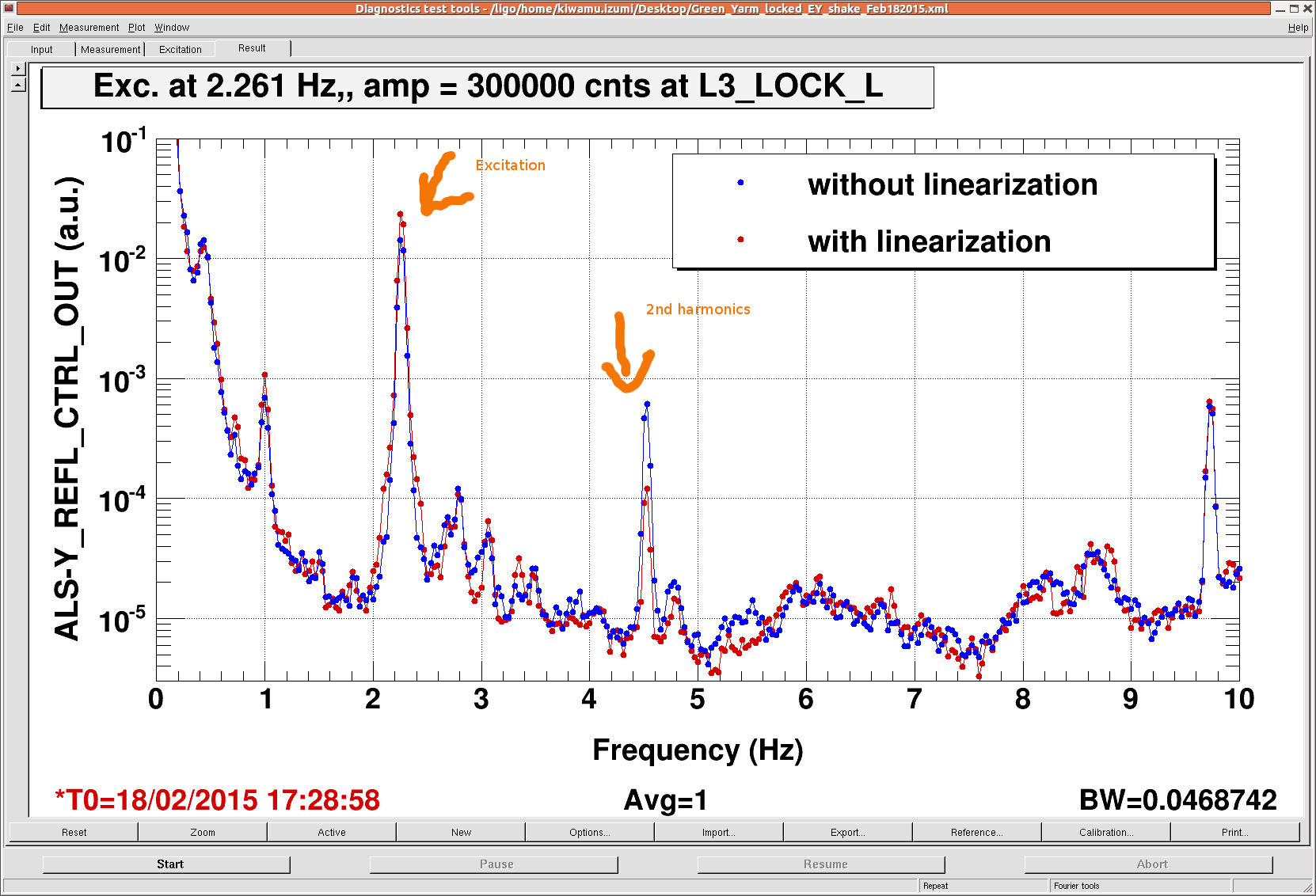
As I switched the linerization on, the peak height at the excitation frequency increased by a factor of roughly 1.65. In addition, the 2nd harmonic peak decreased as the linearization is supposed to eliminate the nonlinear terms. The residual in the 2nd harmonic could be due to some charge on the test mass.
If this is true in ETMX as well, this will reduce the discrepancy between the suspension model and measurement down to 25% (which was previously reported to be discrepancy of a factor of 2.07 in alog 16780).
(Analytical calculation does not match the measurement)
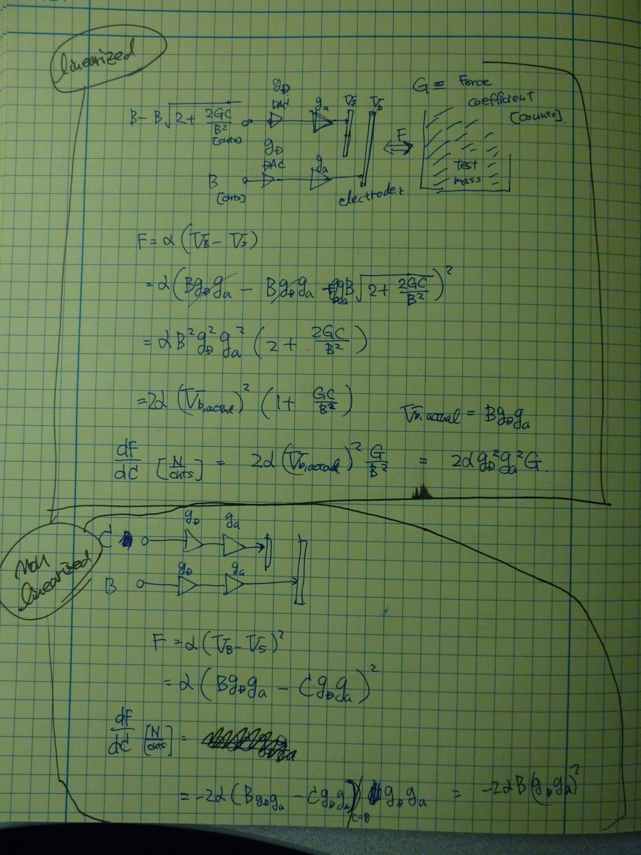
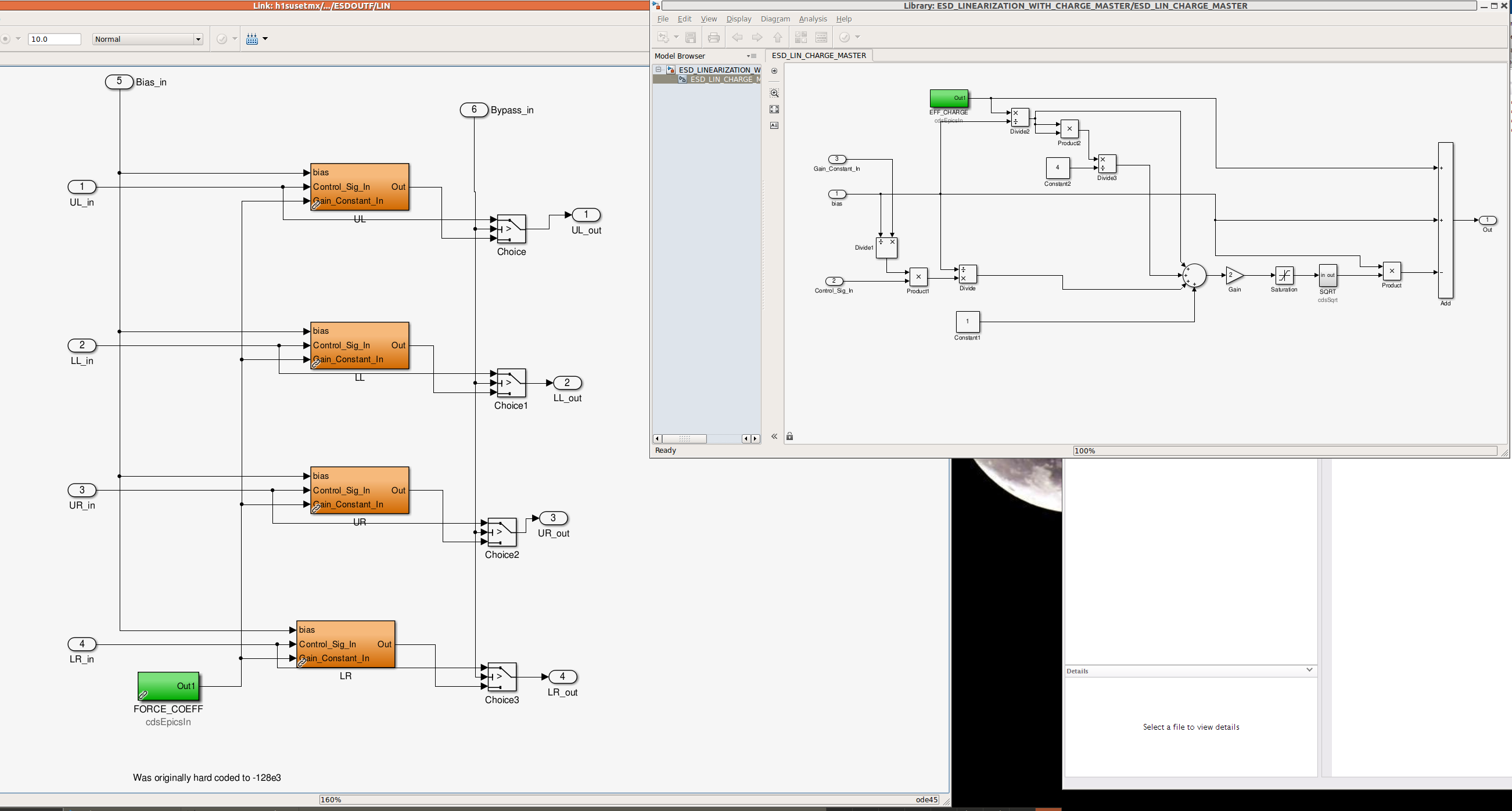
On the other hand, according to my math (see the second attachment), the linerization was expected to increases the response only by a factor of 1.45 instead of 1.65. Although the difference between the two is only 13%, this still makes me think that something is not right as this calculation is relatively straightforward. Just for reference, I also attach the liearization simulink model that we use on ETMs.
If my math is correct, in order for the ESD to have the same actuator response gain, the absolute value of the force coefficient has to be the same as the bias counts at the DAC. Since we use bias voltage of 9.5 V (or 125418.4 cnts), the force coefficient should be -124518.4 cnts as well, but it was set to -1800000 cnts in reality. Since the response gain is proportional to the force coefficient, this should give us an extra increment of 1800000/124518.4 = 1.45 in the gain. I have no idea why the measurement differs from the expected.
I will repeat the measurement at some point soon when I get a chance.
The charge on the test mass is probably affecting your calibration. It would be useful
to measure the charge on all 4 of the test masses using the optical levers and excitation
of the quadrants independently. Look at Stuart Aston's and/or Borja's log entries at LLO and LHO. Also, the charge will be variable as long as the ion pumps are open to the vacuum system.