jeffrey.kissel@LIGO.ORG - posted 18:17, Monday 23 February 2015 (16868)
Prep work for sending ASC to the QUADs, a.k.a. Spelunking to LLO and Checking Applicability to LHO
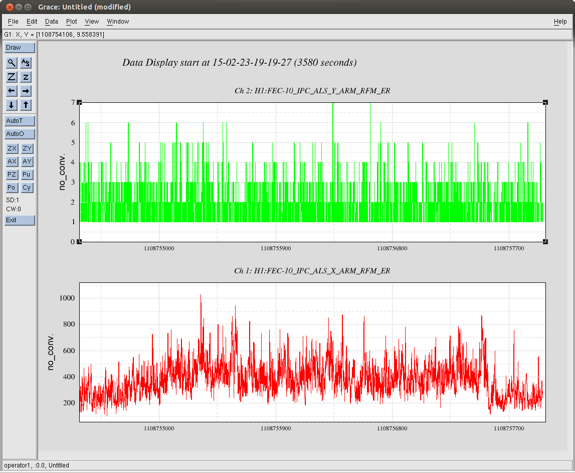
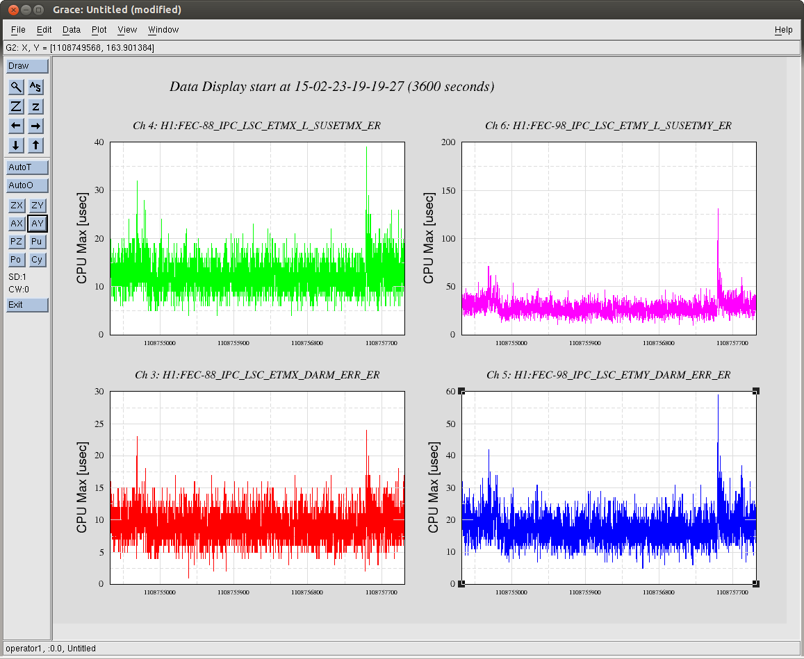
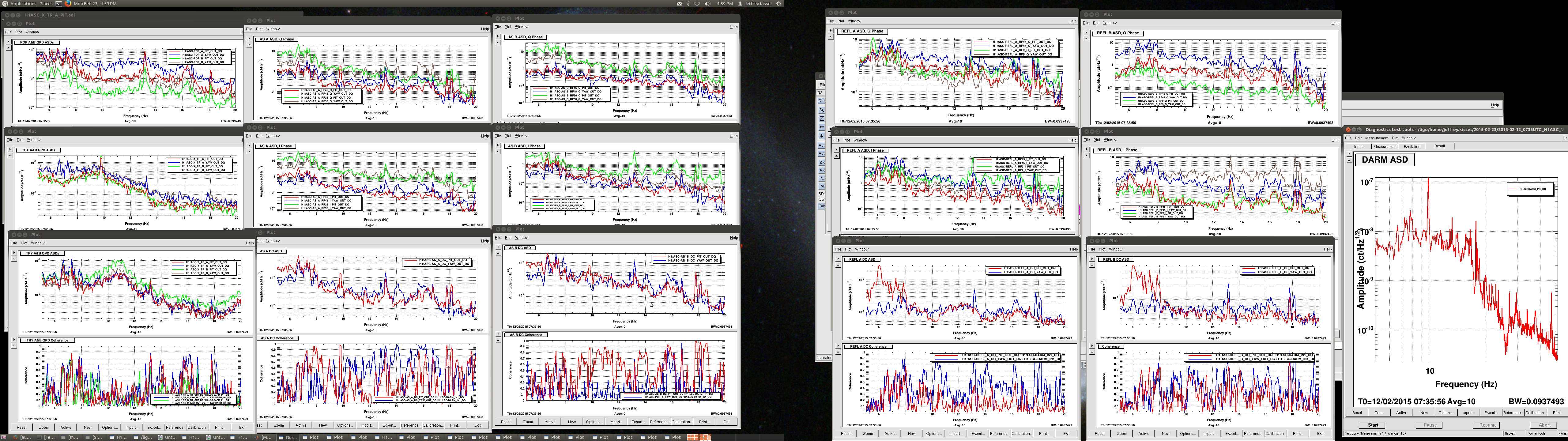
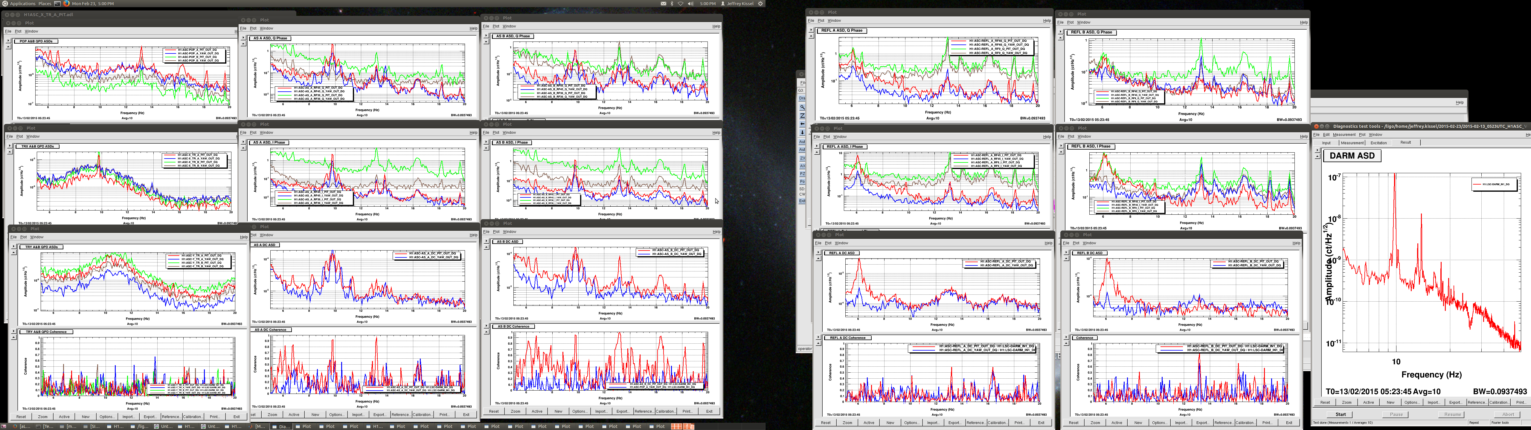
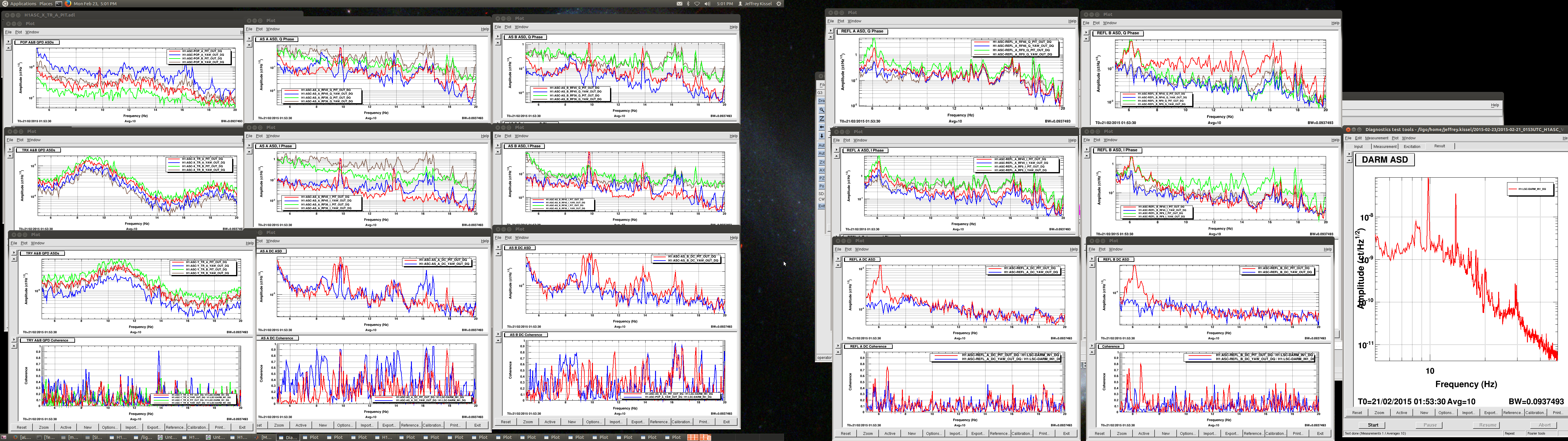
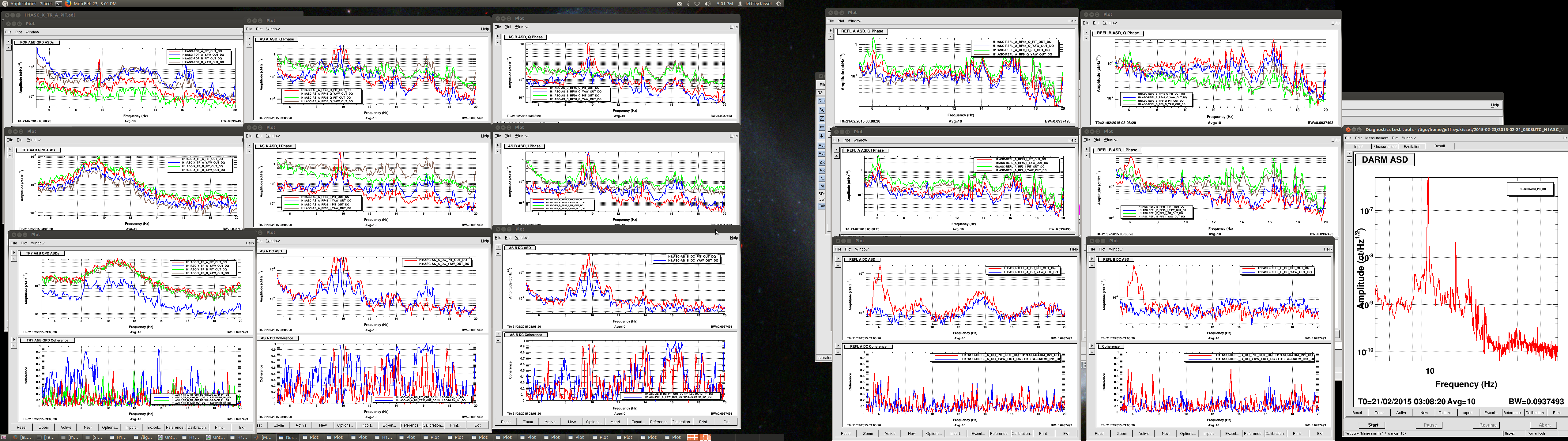
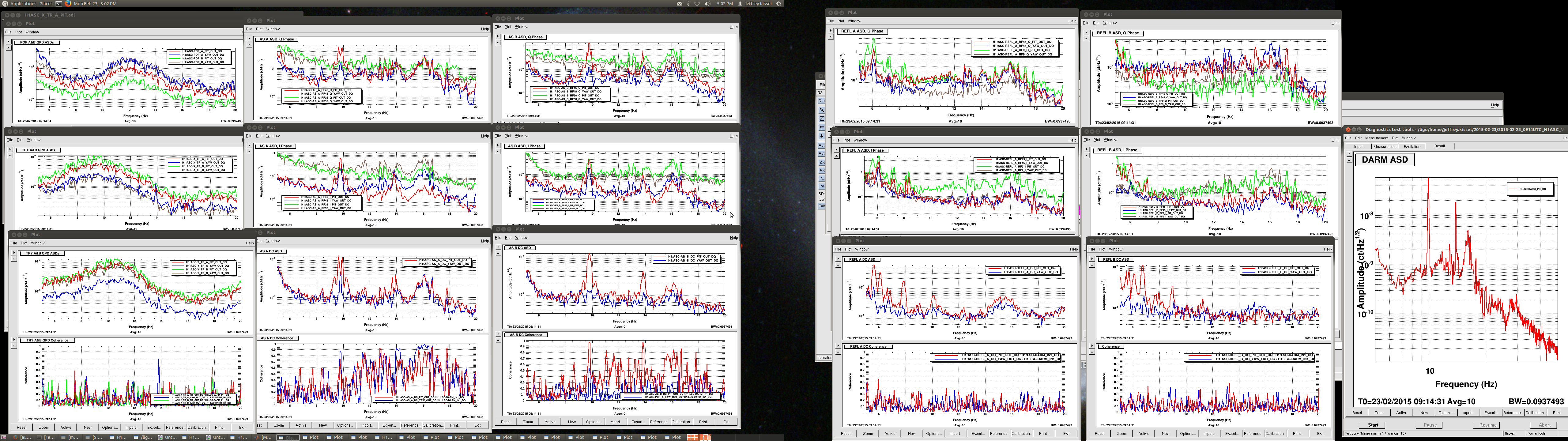
J. Kissel, S. Aston

As per ECR E1500090, Integration Issue 1015, and Work Permit 5069 we are preparing to copy LLO's infrastructure implementation of using AS_A_RF45_Q_PIT (i.e. the pitch signal calculated from the Q phase of the 45 [MHz] demodulated signal from the AS A WFS in HAM6, see D1200666 and T1100472) to damping the four QUAD's roll mode.

However, we found ourselves asking many questions of the implementation, namely if blindly copying is the right thing to do, mostly because of it requiring Reflected Memory (RFM) IPC connections between the ASC model and QUAD models. We think the answer is the blindly copying is NOT the right thing to do. We think we have a better sensor that is more suitable to how the roll modes appear in the H1 ASC sensors, and we think we don't have enough IPC head room. See discussion below.

Please tell us your thoughts on this. If we don't hear any push back by ~9a PT tomorrow morning, we're going forward with the changes to the scheme as decided below.


(1) Recently, LHO has pushed forward many different ways to *reduce* the number of ISC to ETM reflectec memory (RFM) communications:
    (a) We have split the ISC end-station models into two parts, an ALS and ISC model (LHO aLOG 16443)
    (b) We've moved the RFM connection for differential tidal control from being sent directly to the ETMs to being sent to the end-station ISC models first, and then sent to the SUS models via Dolphin PCIE. (T1400733)
    (c) Removed the SEI EX / EY computers from the RFM Loop (LHO aLOG 16775)
    (d) We will be (also tomorrow) re-distributing our corner-station LSC front end models to move the DARM path from the h1lsc.mdl to the h1omc.mdl (E1500041)
Indeed, even LLO -- though they've only found to have *intermittent* IPC errors -- is testing out a faster CPU for their LSC computer to decrease the clock cycle turn around time.
... so, for the two new ASC to ETM RFM connections that LLO has added, should we do the same thing at (2) and feed the RFM connections to the end-station ISC models, and then to the SUS via Dolphin PCIE?

Here is the current status of relevant IPC errors / clock-cycle turnaround time:
              Avg Clock Cycle   IPC Receiving   Channels                            Error Rate
             (CPU Max, [usec])    Errors?                                         [n errors/sec]
LLO  LSC           35               No
     ASC           161              No
     ISCEX         27               No
     ISCEY         25               No
     [ALSEX]     [does not exist]
     [ALSEY]     [does not exist]
     SUSETMX       50           Intermittent  L1:LSC-ETMX_[DARM_ERR,L_SUSETMX]         less than 1
     SUSETMY       49           Intermittent  L1:LSC-ETMY_[DARM_ERR,L_SUSETMX]         less than 1

LHO  LSC           36              Yes        H1:ALS-[X,Y]_ARM_RFM             X: 100 to 1000, Y: 1-10
     ASC           160             Yes        H1:ALS-[X,Y]_REFL_SLOW_RFM                2048
     ISCEX         5               No
     ISCEY         5               No
     ALSEX         32              No
     ALSEY         31              No
     SUSETMX       48              Yes        H1:LSC-ETMX_[DARM_ERR,L_SUSETMX]    1 to 25, 5 to 40
     SUSETMY       49              Yes        H1:LSC-ETMY_[DARM_ERR,L_SUSETMX]   10 to 120, 5 to 60
Reminders:
- all of the above models are running at a sampling rate of 16384 [Hz], so they have 60 [usec] to complete their clock cycle
- all IPCs have a delay of 1 clock-cycle built in, but if all the computations do not complete, or just barely have enough time to complete, then the IPC misses the even the 1 clock-cycle and throws an error
- The RFM loops (there are separate loops for each end station) is now
LSC -> SUSETM[X,Y] -> ISCE[X,Y] -> OAF -> ASC -> LSC
where the delay between the LSC and SUSETM[X,Y], as well as the ISCE[X,Y] and OAF, is the one-way four [km] light travel time through a glass fiber,
n * L / c = 1.5 * 3995 [m] / 3e8 [m/s] = 20 [usec]
and the delay between nodes in the same building is believed to be dt = 0.7 [usec]. This means from the LSC back to LSC delay is
2 * n * L / c + 3 * dt = 2 * 1.5 * 3995 [m] / 3e8 [m/s] + 3 * 0.7e-6 [s] = 42 [usec].


(2) The roll coupling to specifically AS_RF45_Q_PIT is the *only* feedback sensor that's piped to the SUS. But the coupling is a dirt effect do to imperfections in the real system. What guarantee do we have that we'll have equal success with this and only this sensor?
To help answer the question, I took a look at 5 of the more recent times when the IFO was fully locked on DC readout,
(a) 2015-02-12 07:35:56 UTC
(b) 2015-02-13 05:23:45 UTC
(c) 2015-02-21 01:53:30 UTC
(d) 2015-02-21 03:08:20 UTC, and there doesn't appear to be a pattern on where they appear. For example,
(e) 2015-02-23 09:14:31 UTC
in which the there are one of two roll modes visible in DARM: 13.18 [Hz] in (a) and (b), 13.81 [Hz] in (b), (c), (d), and (e). At these times, I've taken a 0.05 [Hz] resolution amplitude spectral density of DARM and *every* ASC channel, i.e.
AS A --  45 and 36, I and Q, PIT and YAW
AS B --  45 and 36, I and Q, PIT and YAW
REFL A --  45 and 9, I and Q, PIT and YAW
REFL B --  45 and 9, I and Q, PIT and YAW
TRX -- A and B, PIT and YAW
TRY -- A and B, PIT and YAW
POP -- A and B, PIT and YAW,
or 52 channels plus DARM, and compared the amplitude and coherence to DARM in these channels for the 5 times. For each lock stretch, when either the 13.18 [Hz] mode or the 13.81 [Hz] mode is visible, it has an amplitude of ~2e-8 [ct] in DARM. After staring at the plots for an hour or three, I've convinced myself (and Stuart) that in 4 out of the 5 lock stretches, either AS B RF45 Q PIT or YAW  is the sensor channel that sees both modes reliably *not* AS A RF 45 Q PIT. Further, observability does not preclude controllability, so it's not immediately clear which of the sensor signals will actually serve well for feedback. Finally, in the 5 lock stretches, only two of the four possible QUAD's highest roll modes have appeared. BUT I tested the hypothesis "does the lower frequency mode appear only in the TRs, and the higher in POP?" on the hunch that those two signals would be able to distinguish between an ETM roll mode or an ITM roll mode: again, I've convinced myself that the lower frequency mode (13.18 [Hz]) is only ever visible in POP -- implying its an ITM -- and the higher frequency mode is visible in the TRs -- implying it's an ETM. Maybe.

Here's my point: if we want to be able to damp both of these modes, then just one ASC sensor isn't the right answer, and which sensor sees the mode the best is IFO dependent.
Images attached to this report