Summary
Using the swept sine injection that was going on during the last DC readout noise, I tried to estimate the coupling of frequency noise to DARM.
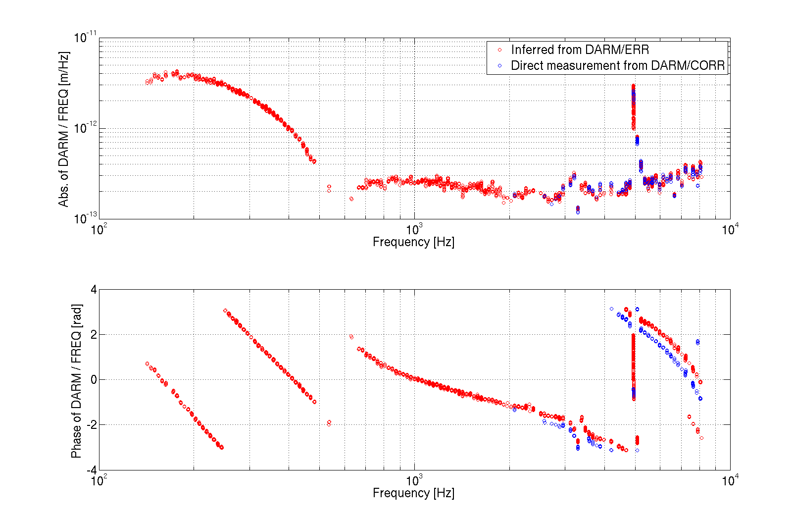
It turned out ot be quite large, at the level of 2e-13 m/Hz above 1 KHz (see first plot). After some discussions and more thinking, we realized that if the IMC longitudinal locking point is not perfectly tuned to the top of the resonance, the IMC will convert frequency noise into intensity noise, and therefore the measure TF is not really the pure coupling of frequency noise to DARM.
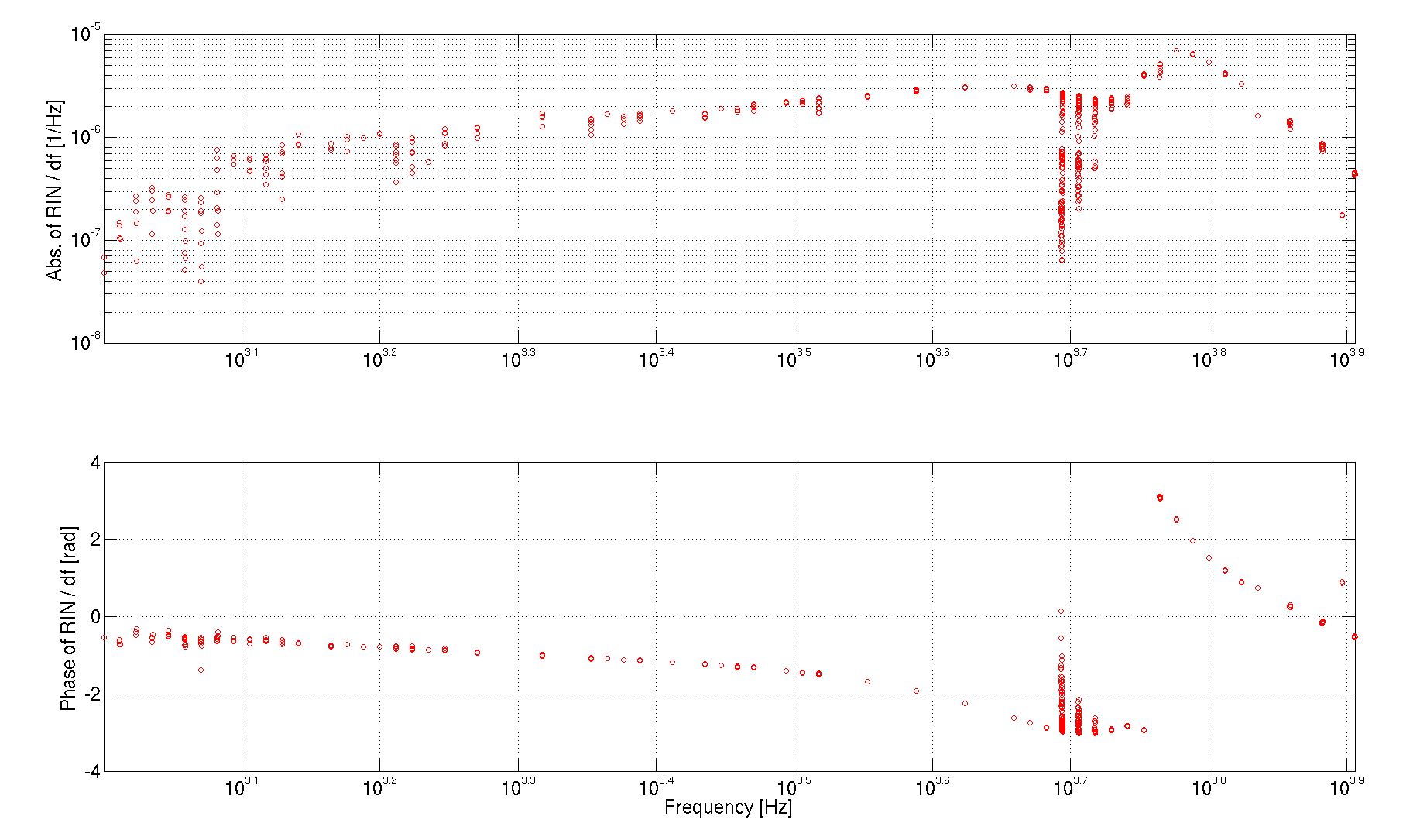
Indeed, the swept sine is very well visible in the IMC transmited power (for example in the ISS signals). I could use the TF from frequency noise to RIN (see second plot) to estimate the IMC longitudinal offset. It turned out to be of the orer of 2e-12 m, which is about 0.5% of the IMC linewidth. This seems quite reasonable. We'll have to retune the IMC locking point in the short term.
This IMC locking offset might be the explanation for the high frequency broad band coherence between DARM and PRCL/SRCL signals.
More details - estimation of frequency noise coupling to DARM
We were injecting the sweep sine into the common board correction, and we were reading the cocrrection after the injection. I could measure DARM using the calibrated signal CAL-DELTAL_EXTERNAL_DQ (after applying a dewhitening in the form of 5 zeros at 1 Hz and five poles at 10 Hz, DC gain of 1). I could measure the actual frequency board correction using IMC-F_OUT which is calibrated in kHz. In this way, the transfer function from the common board correction to DARM is a direct measurement of the coupling F of frequency noise to DARM. Unfortunately, I could get coherence only above 1 kHz. I could get better coherence between the common board error signal and DARM above 100 Hz. This transfer function is F/G, where G is the response of REFL_9_I to freqeuncy noise at the IFO input. This is described by the double cavity pole, which is quite well described by 1/(1i*f) at frequencies above 100 Hz. So I can match the high frequency of DARM/IMC-F_OUT and DARM/LSC-REFL_SERVO_ERR (corrected for the pole) to get another estimation of F, valid from 100 Hz and up. I also can get a measurment of G which is 6e8 / (1j*f). The result is shown in the first plot.
More details - estimation of the IMC longitudinal offset
I can estimate the coupling of frequency noise at the IMC input to intensity noise at the IMC output with the transfer function between IMC-F_OUT and PSL-ISS_SECONDLOOP_SUM14_REL_OUT (which is calibrated in RIN). I get something of teh order of 1e-6 1/Hz at high frequency. The TF is not completely flat, but let's ignore this for the moment being.
If the IMC is locked off resonance, I get a direct coupling of frequency noise to intensity noise given by
dP/p = 32 Finesse^2 L_IMC / (lambda * c) * offset * frequency_noise
So I get the estimate of the offset to be of the order of 2e-12 m, to be compared with the linewidth lambda/4/Finesse = 5e-10 m