Sheila, Evan, Elli
We adjusted SR2, SR3 alignment sliders to center the beam going into the output faraday and to maximise light going into the OMC DCPDs. This was done with a straight shot through the sorner sation with BS, ITMY aligned, SRM, PRM, ITMX misaligned. The input laser power was 10W. We used the ASC wfs DC centering servos and the OMC dither align.
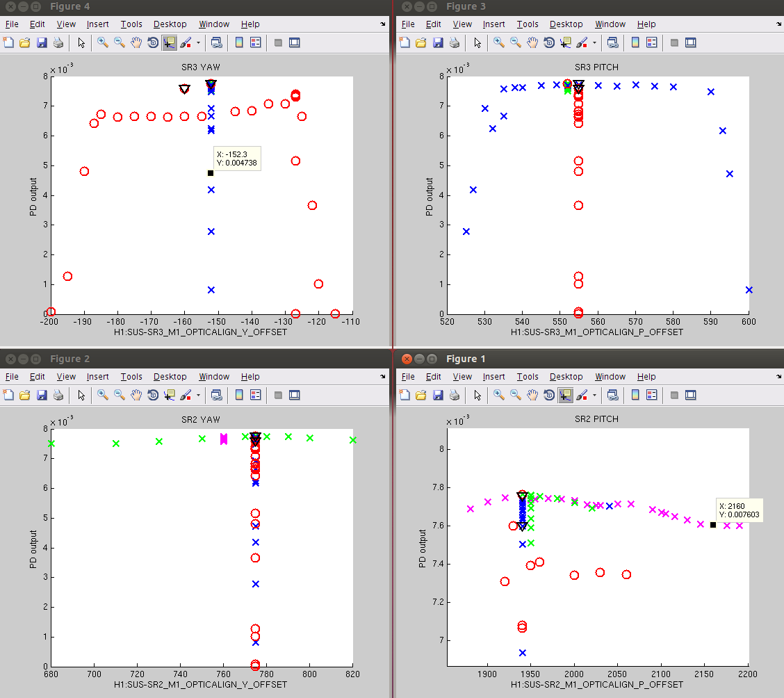
We moved SR2 pitch, SR2 yaw, SR3 picth, SR3 yaw alignment offsets one at a time and located the alignments the power on the DCPDs started to drop off. There is about 70 microradians of range for each degree of freedom where the power is high (see screenshot). We picked alignment values in the center of these ranges where the OMC DCPD power is also maximised. The maximum power on H1:OMC-DCPD_A_OUT_DQ was 7.7e-3 counts in this configuration.
Changed values are:
| channel name | old value | new value |
| H1:SUS-SR2_M1_OPTICALIGN_P_OFFSET | 2100 | 1940 |
| H1:SUS-SR2_M1_OPTICALIGN_P_OFFSET | 760 | 775 |
| H1:SUS-SR2_M1_OPTICALIGN_P_OFFSET | 551.9 | 555 |
| H1:SUS-SR2_M1_OPTICALIGN_P_OFFSET | -152.3 | -152.3 |
Sheila then used the picomotors to center ASC-AS_C qpd, so we can use this to check the alignment into the output faraday. Afterwards, Evan and Sheila re-centered the beams on the ASAIR photodides and the ASAIR camera.