richard.savage@LIGO.ORG - posted 15:07, Monday 09 March 2015 (17145)
Pcal problem solved
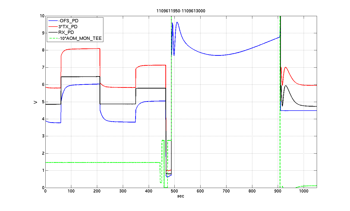
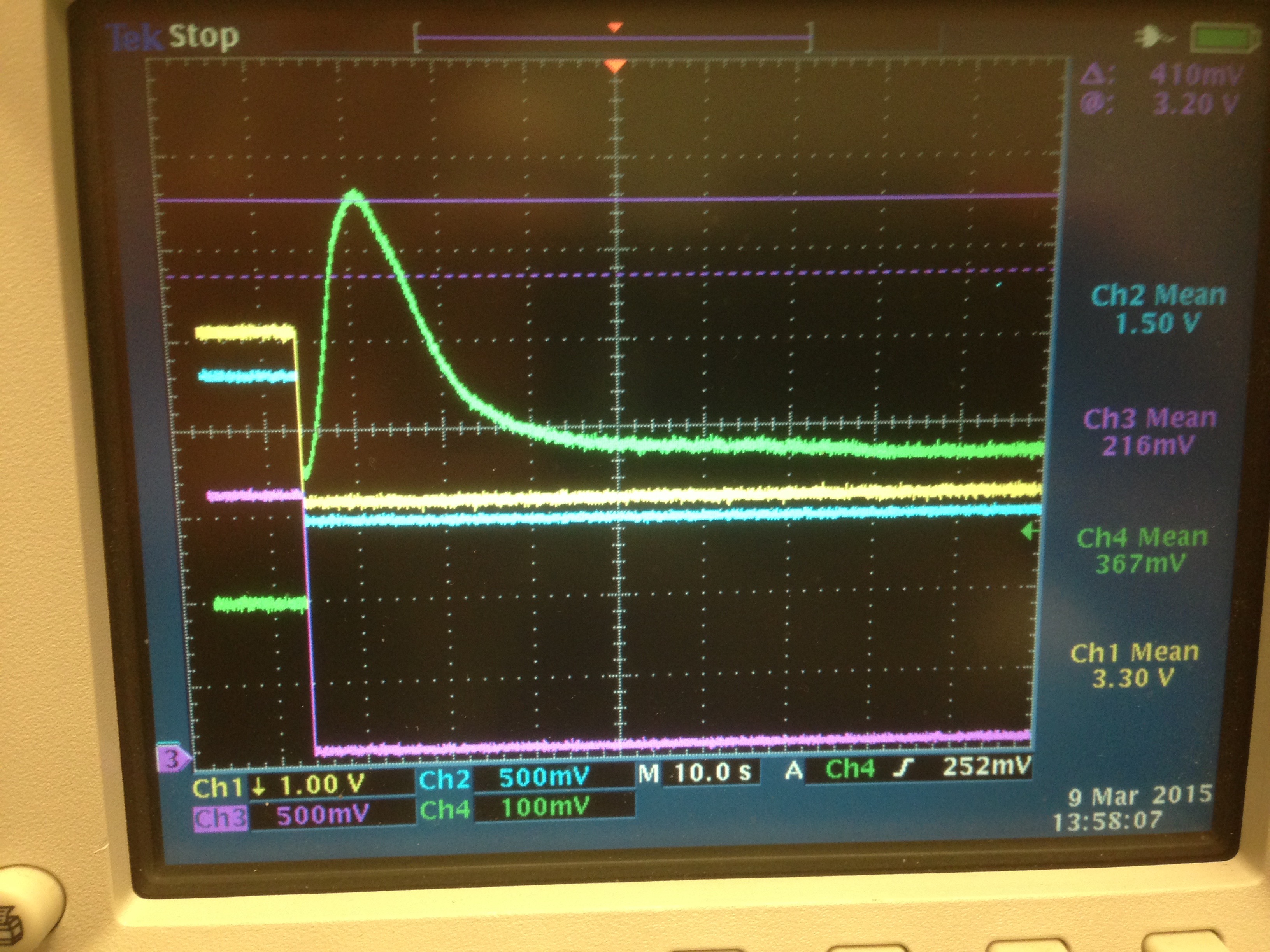
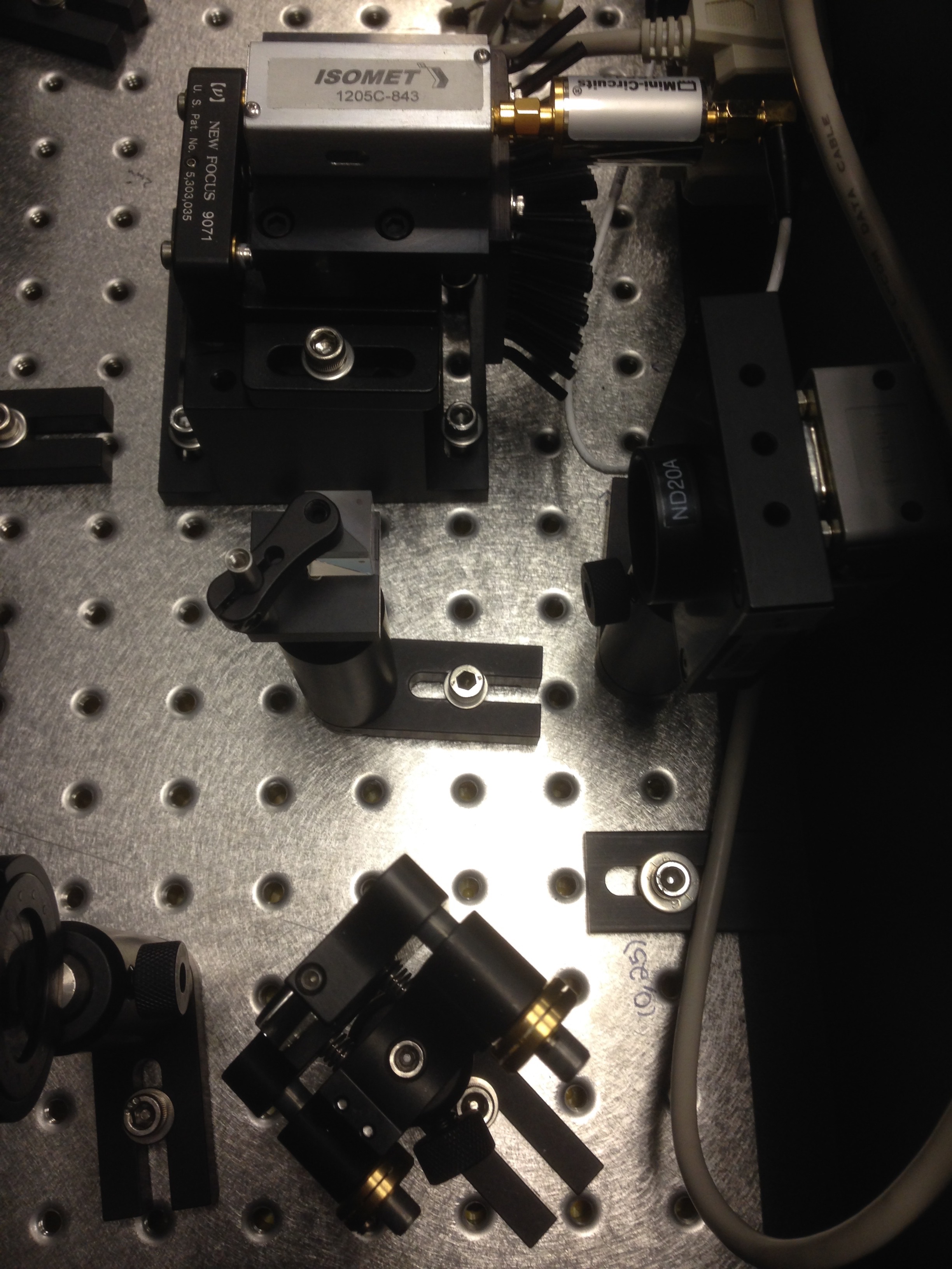
SudarshanK and RickS

Since first noticed during the LLO Yarm commissioning effort two weeks ago, we have been chasing a subtle problem that is confusing the Pcal calibrations.

Today, we finally found the source of the problem, and fortunately it has a relatively simple remedy.

The Pcal transmitter modules use uncoated, 3 deg., BK7 glass wedges to generate the sample beams for the Optical Follower Servo (OFS) and Transmitter (Tx) Monitor photodetectors

The wedge is operated near Brewster's angle to reflect only about 0.1% for the OFS PD (first surface) and 0.5% for the Tx PD (second surface).  We have been observing slow (few to tens or even hundreds of seconds) transients in the OFS and Tx PD signals that have apparently resulted from fast, large-amplitude changes in the OFS signals, e.g. from changes in the loop gain or offset.

We have been making measurements to eliminate potential offenders and today we tracked the source of the slow variations we have been seeing to small, time-varying depolarization of the Pcal beams caused by the acousto-optic modulator (AOM) that generates the Pcal beams that are directed to the ETMs.  This depolarized light, while only a few tenths of a percent of the incident light, is in S-pol when incident on the wedge beamsplitter, so about 10% of it is reflected to the photodetectors.  By installing a polarizing beamsplitter cube downstream of the AOM the slow transients in the Pcal beams were eliminated (or at least significantly reduced - we will investigate further).

The attachment below shows StripTool trends of the H1 Y-end Pcal OFS, Tx, Rx (receiver), and AOM drive monitor signals when the AOM drive level was changed (left half of figure, up to 450 seconds), when the loop switch was closed but the loop had not locked (490-910 dseconds), then when the loop locked after the offset was adjusted (910 seconds).  Note that the OFS PD signal (blue trace) goes flat when the loop closes, but the drifts in the OFS PD signal due to the AOM-generated S-pol light is imposed on the other "out of loop" signals.

The second attachment is an oscilloscope screen photo taken after installing a polarizing beamsplitter (PBS) cube downstream of the AOM.  The green trace is from a temporary photodetector that was installed in the beam reflected from the PBS (s-pol light), yellow is the OFS PD, the blue trace is the Tx PD, and the magenta trace is the monitor of the drive to the AOM modulation input (modulates the amplitude of the 80 MHz RF).  Note that the s-pol light exhibits the long (10s of seconds) transient observed at LLO and at LHO.

The third attachment is a photo of the lab setup with the PBS and temporary photodetectors installed.

We have packaged two complete PBS hardware setups along with beam dumps for the reflected beams.  They will go out to LLO to Shivaraj's attention via overnight delivery tomorrow for installation ASAP at LLO.  We plan to install an identical setup at LHO Yend later today or tomorrow morning.  If we find that this is a suitable remedy, we will procure more hardware for LHO Xarm and the 3rd. interferometer.

One of the working standards is currently at LLO.  The Pcal calibrations will have to be repeated.  This should take about two hours at each end station.  We plan to repeat the LHO Yend calibration tomorrow.
Images attached to this report