More details on the scattering Dan mentioned on Friday, with some new and re-interpreted details (the responsible motion is horizontal) that became clear after further investigation.
This last Monday, DARM spectra showed a double scattering shelf occasionally reaching 60 Hz and 120 Hz (Figure 1) and even higher. I searched for the source of the scattering path length variation by looking for motion sensors that detected maximum motion at the times that the higher frequency scattering shelf reached its highest frequency. The top trace of Figure 2 is a 700s time series of DARM, band passed between 90 and 145 Hz. Each of the spikes in the time series was produced when the scattering shelf reached into this band. The lower plot shows that the maxima in one of the OMC OSEM signals coincides with the spikes in the DARM plot above it. All OMC OSEMs show this correlation except the side sensor (on the short side). I found no other GS13 or OSEM channels that showed this correlation; most importantly, it was not in the GS13 signals from HAM6. Figure 3 is a zoom in to one of the clusters of scattering spikes, showing that the scattering spikes appear to occur at the steepest part of the OSEM signals (when velocity would be highest), and that the time spacing between DARM spikes agreed with the resonant frequencies of the OMCS. Beating between 2 of the suspension modes seems to cause the variation in motion.
Using the 1 um/count calibration of the OSEM OUT channels, I obtained average velocity spetra that, for some OSEMs, reached 10 um/s (Figure 4).
In order to produce a shelf out to 60 Hz, the rate of path length change for a single bounce would have to reach about 30 um/s. The OSEMs measure displacement of the top mass, M1, and the OMC hangs below it. At the resonant frequencies of this suspension, the motion of the OMC, while damped, would still be greater than the top mass. Also, the 10 um/s figure is only an average rms. Thus the OMC motion can account for the 60Hz shelf with a single reflection.
There are two shelves in Figure 1 spaced by a factor of 2 in frequency. The spectrogram in Figure 5 shows that the frequency spacing of the two shelves is always a factor of 2. The shelf at 120 Hz in figure 1 is about an order of magnitude below the shelf at 60 Hz. If this represents a scattered beam that reflects twice instead of once, then the reflectivities at each of the two extra surfaces would have to be very high. While there may be other mechanisms to generate the double shelf, it is probably worth looking for bright beam spots on highly reflective surfaces in HAM6.
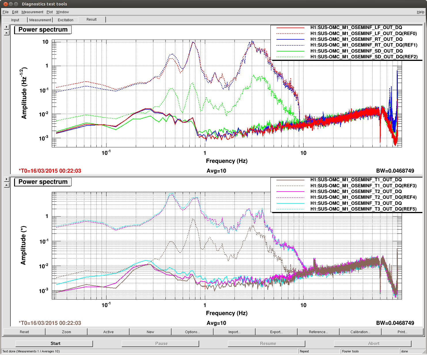
Finally, it would be nice to reduce the motion of the OMC by a factor of ten, particularly, the side to side and rolling motion perpendicular to and about the line connecting the two suspension points of M1, motion detected by the LF, RT, T2 and T3 OSEMs.

It's likely the OMC ASC control (Kiwamu, Daniel, Keita)
Summary:
OMC BOSEMs are usually very quiet, but they show extremely big motion that Robert showed only when the IFO is in lock with DC. In-lock VS out-of-lock ratio is huge at about 3 orders of magnitude.
It turns out that this comes from OMC ASC control actuating on the OMC suspension.
OMC YAW has a large coupling to the distance between the OMC and the IFO because the rotation axis is fairly distant from the first steering mirror on the OMC breadboard, probably 18cm or so, and therefore is likely this is the main motion coupling to the scattering path modulation.
Apart from identifying the scattering source, there could be some mitigation tasks that we could do.
- Stop using OMC SUS for alignment, and instead use to TTs for OMC. This will leave only one TT for AS AFS centering, but our guess is that it's going to be fine.
- If we need to use OMC SUS, we could change the output matrix such that the OMC ASC YAW induce the rotation around the first steering mirror on the OMC.
- Look at the S/N of the ASC, and see if the bandwidth of OMC ASC is appropriate.
We will test the two TT mitigation tomorrow.
Details:
Attached shows the same OMC BOSEM velocity signals that Robert used (the only difference is that this is calibrated in um/sec, not m/sec).
Solid lines are now, broken lines are when Robert took his measurement. At around big peaks, there's 3 orders of magnitude difference. It turns out that they're mostly like solid lines show, and becomes excited only when in DC-lock.
Kiwamu will fill in more details.
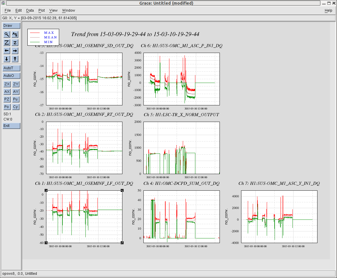
I attatch a 24-hrs trend of some relevant channels from Mar-10-2015. As shown in the trend, it seems that every time the OMC-ASC loops are in action actuating on the OMC suspension, the OMC OSEMs read high fluctuation as weel as a big shift in the DC values. When the OMC ASC loops are not in action, the OSEM readouts are quiet.
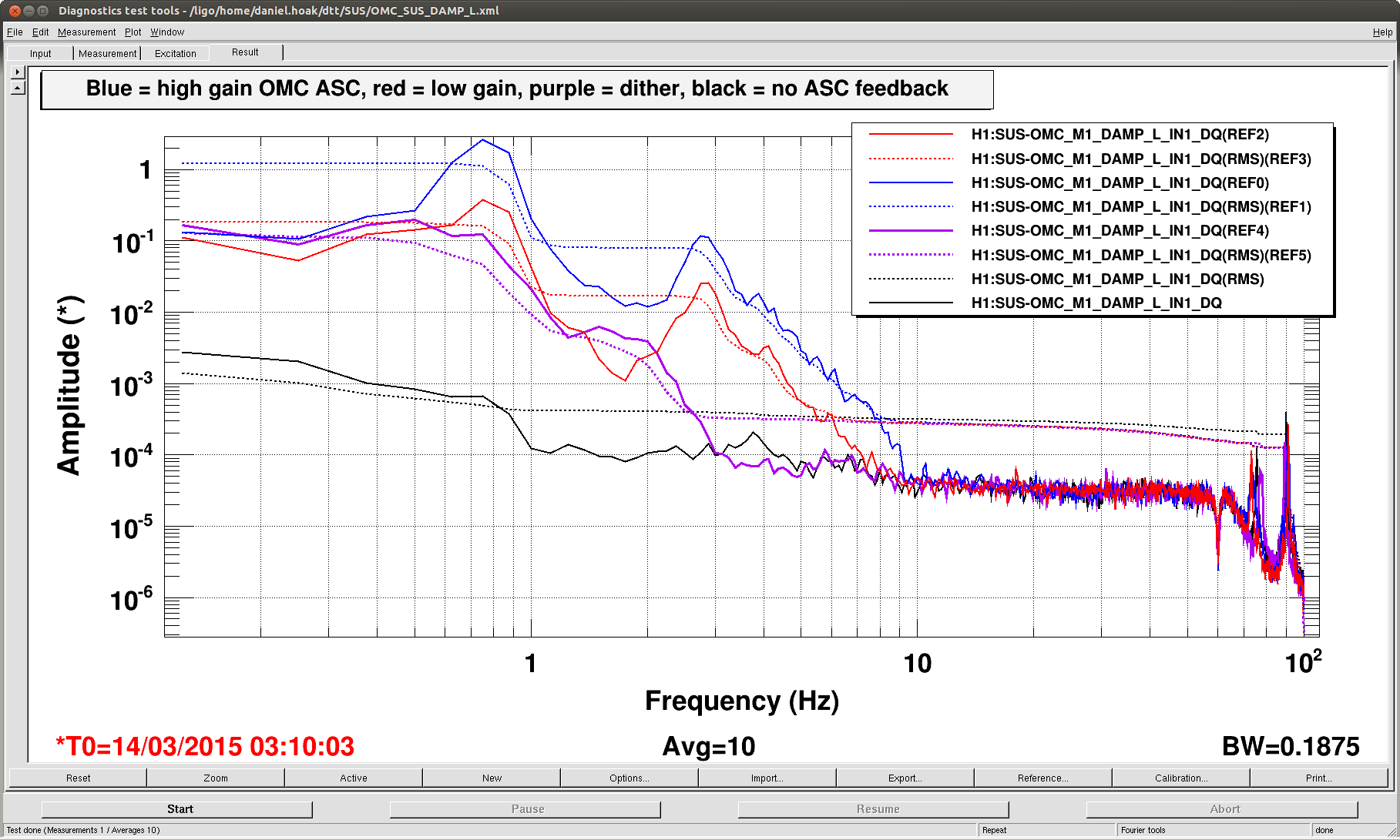
On Friday we reduced this scattering noise below the usual noise floor by reducing the OMC ASC gain by ~10x. This reduced the UGF of the QPD loops down to 0.1Hz. This is around the UGF of the dither loops, which explains why we only saw this noise recently, when the QPD loops were used in low-noise. See the attached plot of the OMC SUS longitudinal signal: the blue traces are the QPD loops in a high-gain state, red is low-gain. The purple traces are from March 4 when the OMC was aligned with the dither loops 9 (the dither signals are rolled off above 2Hz since the signal-to-noise above that frequency is not good). The black traces are the quiescent OMC SUS noise without ASC feedback. For the current noise floor between 10-100Hz, the motion of the red and purple traces are low enough to keep the scattering from being the limiting noise source.
That said, this scattering knowledge means that the experiment of feeding back alignment signals to the OMC SUS should end. I've added OM3 to the ASC model, so we can feed back the DC centering signal from AS_B to OM1-3, along with the two degrees of freedom from the OMC. This will give us a 3x3 control matrix for the HAM6 alignment, similar to what's being done at L1. It ignores the centering on AS_A, but centering on AS_B should be sufficient.
Btw the dither loops need to be re-commissioned because I moved the dither lines up to ~1.7kHz. This changed the sensing matrix, it needs to be remeasured and inverted for a new control matrix. Tomorrow we will 1) switch the control topology to use the OMs rather than the OMC SUS, and 2) switch the sensing topology back to the dither for low-noise operations.