In the past two or three days, Sheila, Dan and I have worked more on switching of the ETM actuators from the ESD to L2 stage with the goal of reducing the ESD DAC noise (see Evan's latest noise budget). Last night, I was again able to reduce the ESD biases all the way to zero by actuating on the ETMY L1 and L2 stages (see previous attempts in alog 17267). The DARM spectrum improved in 30-200 Hz band as expected, but only by a factor of ~ 1.7. Lock was not so stable (which seemed to be related to a peak at 12.52 Hz) and it stayed locked only less than 10 minutes. I was not able to test different bias voltages yet.
(DARM noise)
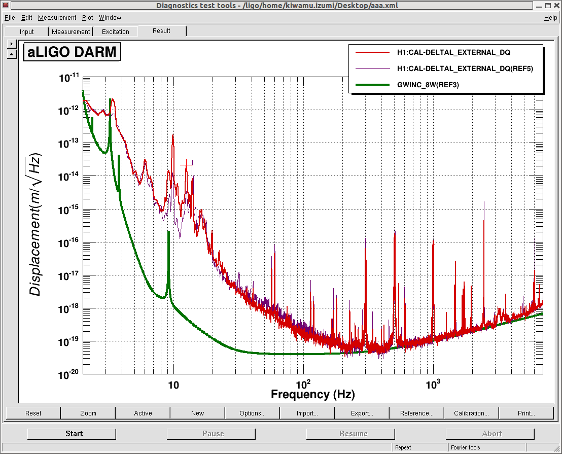
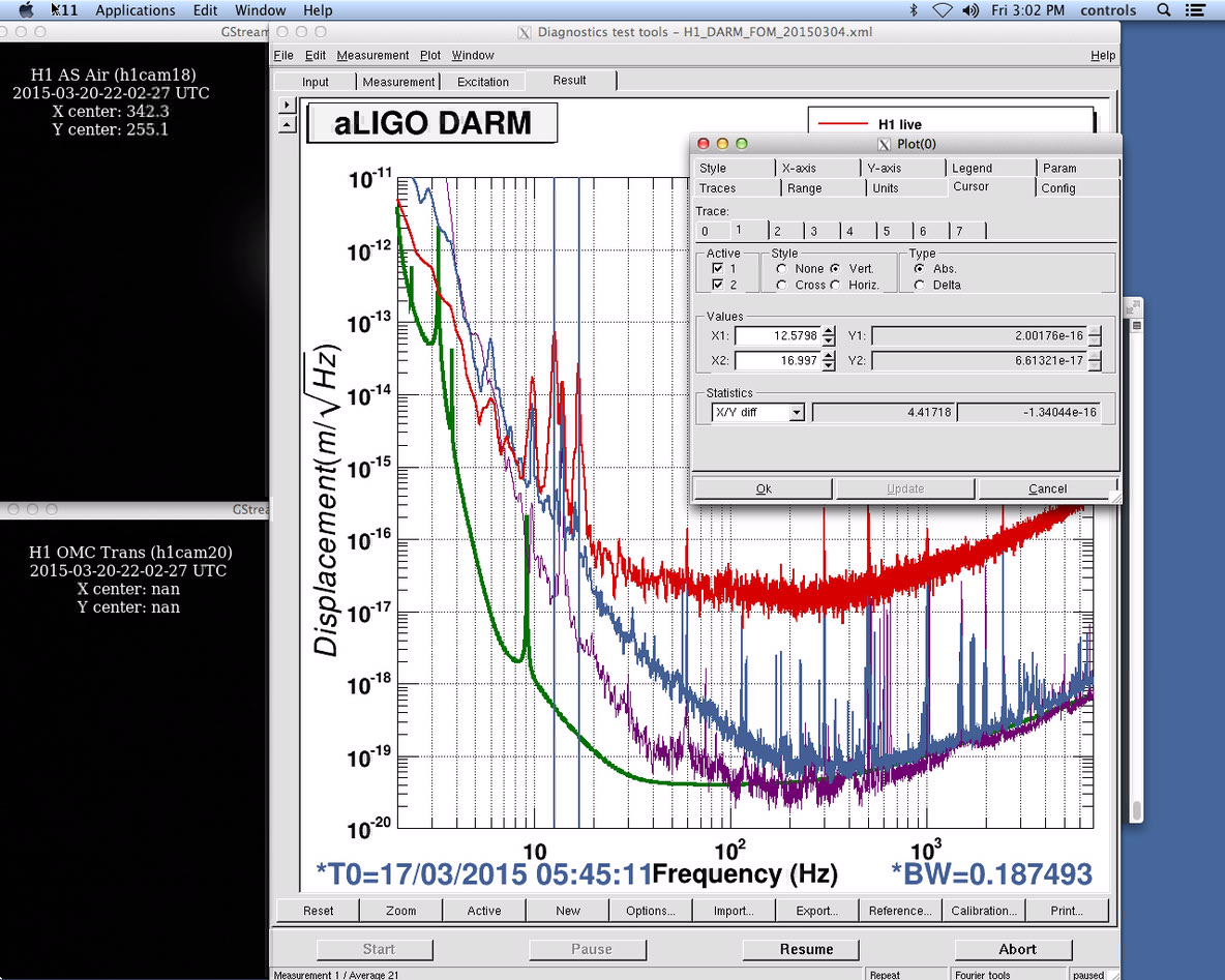
Here are two DARM spectra, one with the 380 volts ETMX ESD bias (in purple) and the other with zero bias voltage (in red). The ETMY ESD had zero DAC voltage in all the quadrants and bias all the time. As you can see, the noise floor went down in 30-200 Hz band with a slight increase at around 20 Hz. Also a peak at 12.5 Hz has been prominent in this week (for example, look at alog 17355) and it looks like this peak rings up every time before we lose lock. The peak usually becomes clearly visible in the DHARD signals in time series several seconds before the lock loss.
(Actuation Scheme)
We used to switch off the ETMX ESD and switch on the ETMY L2 stage while keeping the ETMX L1 stage active (see alog 17267) in the last week. This time, we tried a different scheme in which we actuate the L1 and L2 stages of ETMY and we do not actuate ETMX at all. In a sense, this is a transition of the ETM suspensions from X to Y. Before trying the transition, we measured the transfer function of the L1 and L2 stages at different times in order to check the cross over frequency. The attached below is the ratio of the two transfer functions (i.e. L1 / L2) together with a LSC DARM open loop, L1 and L2 transfer function models:
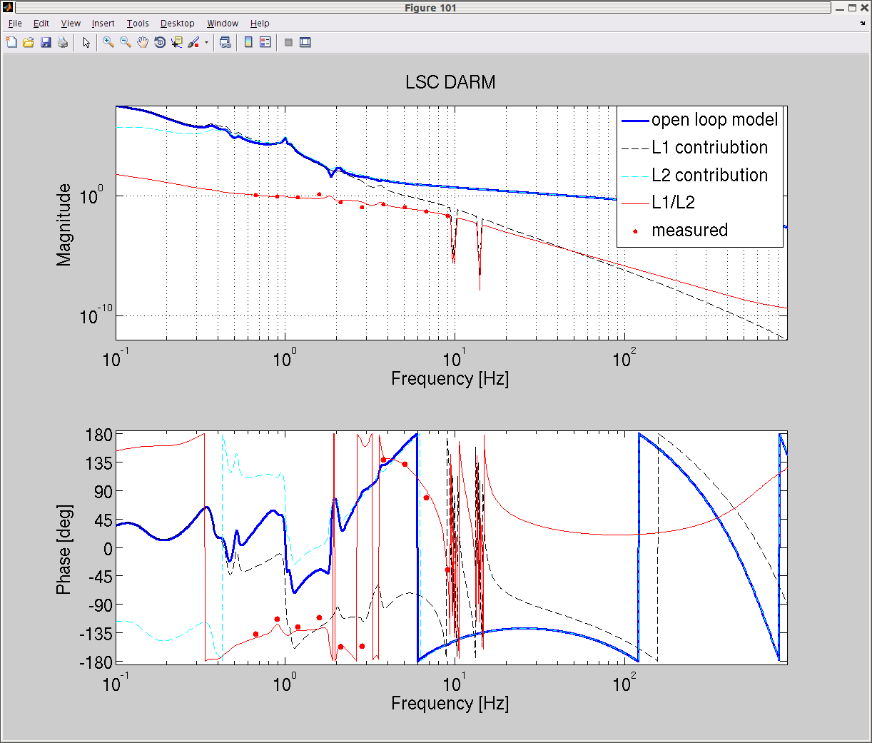
As shown in the plot, the measurement can be mostly explained by the model. However, according to the model, the phase at 1.8 Hz touches 180 degrees and thus unstable at this frequency. Unfortunately our measurement incidicated that the ratio of L1/L2 exceeds unity gain at around 1.6 Hz and I noticed that this would be a potential risk of unstable loop. Indeed, this configuration gave me unstable DARM which rang up at 1.6-ish Hz as expected when I tried transitioning to ETMY. I decided to insert a lead filter around this frequency. With the lead filter (a simple zero-pole pair at 0.3 and 1.5 Hz respectively), the L1/L2 transfer function should now look like the following:
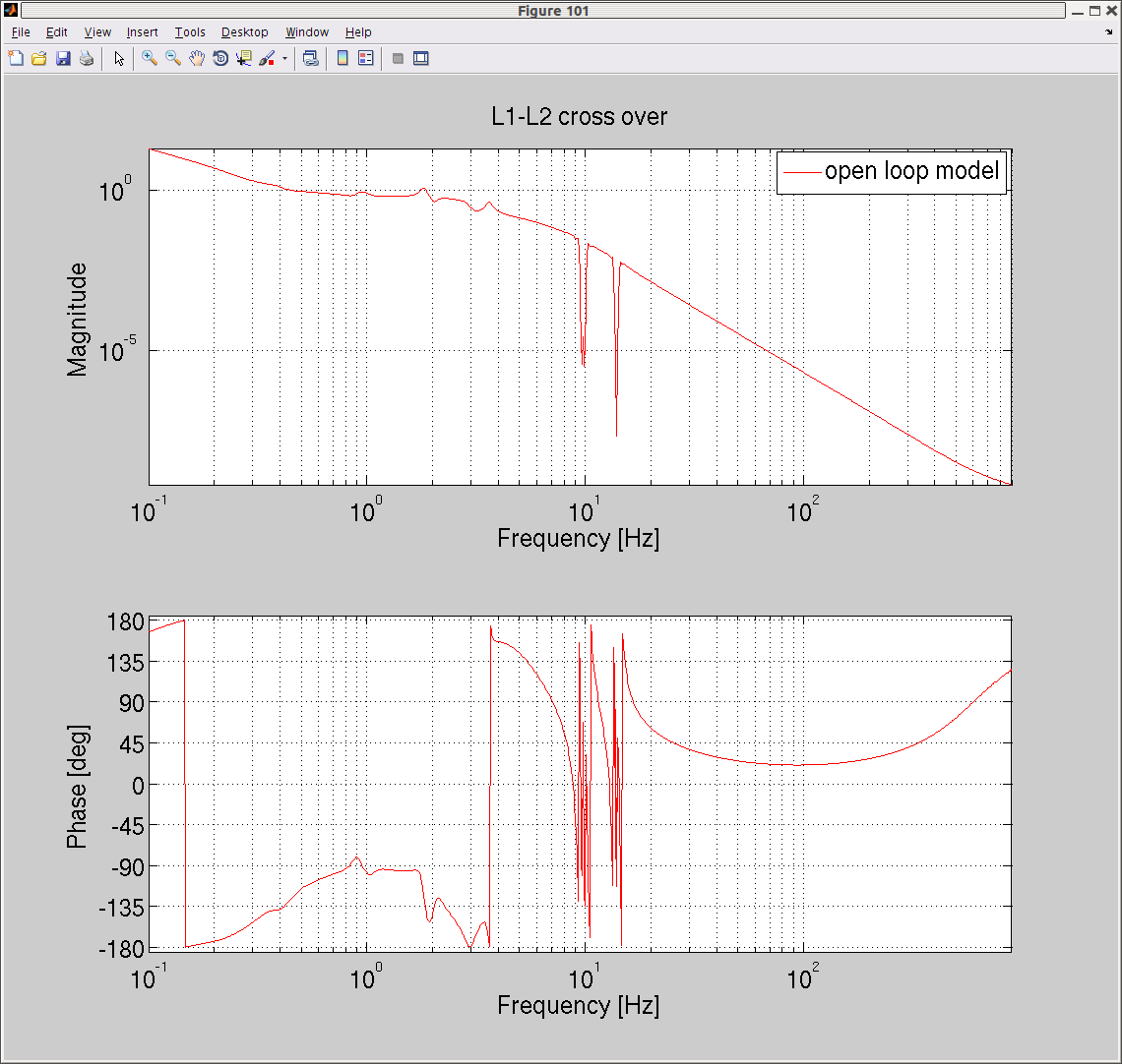
This has two cross-over points, one at 0.45 Hz and 1.8 Hz with phase mergines of 57 and 43 degrees. I installed the lead filter in FM8 of SUS-ETMY_L1_LOCK_L. This allowed a repeatable transition. The transition process is also coded in the ISC LOCK guardian.
Fred, Kiwamu,
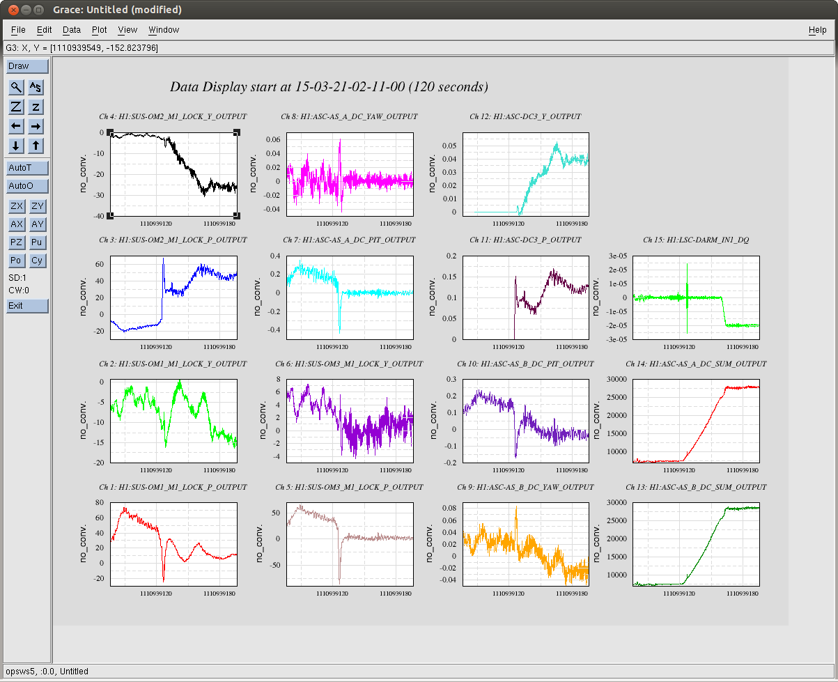
So the 12.5 Hz oscillation happens not only when the interferometer is locked on DC readout but also when it is locked on ASQ. We had more than three times of lock losses today where we lost lock right after (typically in a few seconds) the 12.5 Hz peak rang up. Taking a close look, we noticed that a 17 Hz peak also rang up at the same time. This two-peaks-behavior seems consistent in each lock loss. Their peak heights typically show a slow modulation in the DARM spectrum (on the order of a few seconds) and eventually reaches as high as 10-13 Hz/sqrtHz (0.3 Hz fft-bandwidth) at which we lose lock. The attached is a screenshot of the DARM spectrum from a time when the interferometer was almost unlocking.
It turns out these 12 and 17Hz oscillations were my fault. Earlier in the week, we switched the HAM6 DC centering toplogy to use AS_A and the OMC degrees of freedom. But, I forgot to edit the part of the DRMI Guardian that sets the ASC input matrix. As a result, for the past two days we have been asking the DC3 centering loops to center the beam on AS_A, but we weren't giving them any input. With the correct DC centering loops on the instability does not appear.
We were able to replicate the 12Hz oscillation by disabling the AS_A centering loop before we increased the power. Also I was able to make it reappear by putting an offset into the AS_A pitch setpoint. At 10W input power, an offset of 0.1 counts was sufficient to excite whatever this mode is and break the lock. This is kind of a small offset - we should figure out how much margin we have during normal operations.
(It could be that we're sensitive to the spot position on AS_B, since any offset in the centering loops will also move the beam on AS_B. But we think that this noise comes in through DHARD, and that error signal is derived from AS_A. AS_B is used for MICH and SRC1.)
Attached is a trend around the time when we saw the oscilation grow during the first steps in the power-up sequence. The DC3 centering loops are turned on about halfway through the trend, and the spot on AS_A is immediately servoed to zero.