In an effort to increase the unity gain frequency of the TTFSS, I had tried a higher resonant frequency but
broader notch filter comprising of a 30 uH inductor for L2 and a 1500 pF capacitor for C16. After re-installing
the TTFSS, I found that the frequency no longer locked. Thinking that it was my circuit modification that was
the root cause, I reversed the changes and found that the frequency servo still did not lock.
The error signal was present when the cavity was swept. Each time the servo was engaged it did not lock
as the slow actuator ramp passed the resonance, which to me indicated that there was no feedback. The
problem was traced to the loop switch not engaging, this in turn was a faulty opto-coupler in the FSS fieldbox.
Coincidentally, the same one that Evan and I had switched the other day. Replacing both opto-couplers and
re-engaging the loop switch, the frequency servo locked.
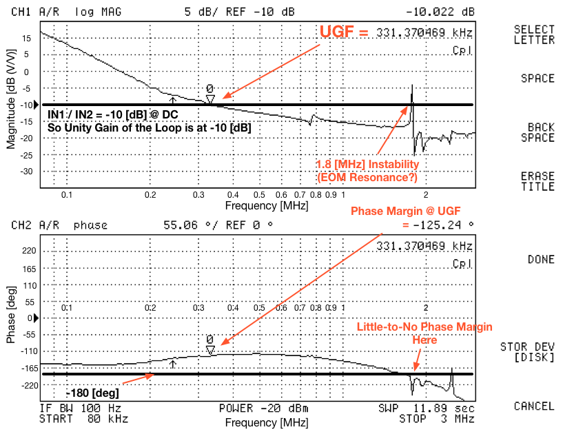
The file M10P5.tif shows the open loop transfer function with the common gain set to -10 dB and the fast gain
set to +5 dB. The presence of the peaks at ~770 kHz and ~1.8 MHz suggest I did not correctly solder in the
two notches.
At the moment the common gain is set to -10 dB and the fast gain to +6 dB. If the loop starts oscillating -
indicated by a wildly oscillating reference cavity transmission of the PZT monitor plot on the MEDM screen
being a solid black, the fast gain needs to be reduced until the oscillation stops and then slowly restored.
The reference cavity transmission was ~1.45 V.
Peter, Rick

I spoke with Evan just to make sure I understood the conversation and implications of this log, and in doing so I've annotated the plot that Peter attached. Hope this helps!

The problem is that this 1.8 [MHz] feature has left the FSS is only marginally stable (it works, but it's unclear whether IFO or IMC lock-losses cause (more) oscillations (than usual)).

Peter will attack again in the morning.