This morning and early afternoon I worked on the IMC alignment. My goal was to reduce the coupling of input beam jitter to intensity noise in transmission of the IMC. In brief, I dithered the input beam with the PZT at 80 Hz in pitch (amplitude of 3 cts.) and at 110 Hz in yaw (amplitude of 2 cts.) and looked at the ISS second loop power. I wrote a python script to demodulate the ISS second loop signal at tghose two frequencies, so that I could produce two error signals. They turned out to be very sensitive to the IMC alignment.
Improving intensity noise with MC2_TRANS beam position (failed)
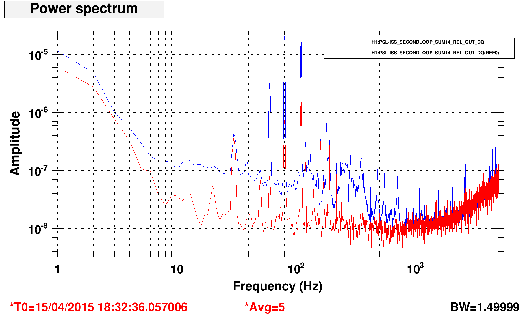
My first attempt was to move the beam on MC2_TRANS QPD in order to minimize the jitter to RIN coupling. Practicallt, I moved the QPD offsets to zero the error signal produced as explained above. The script I wrote implemented a slow servo to do this automatically. As shown in the first plot, this worked fine: this is a comparison of the RIN before and after the adjustment of the beam position. RIN is a factor 10 lower than before almost everywhere below 200 Hz.
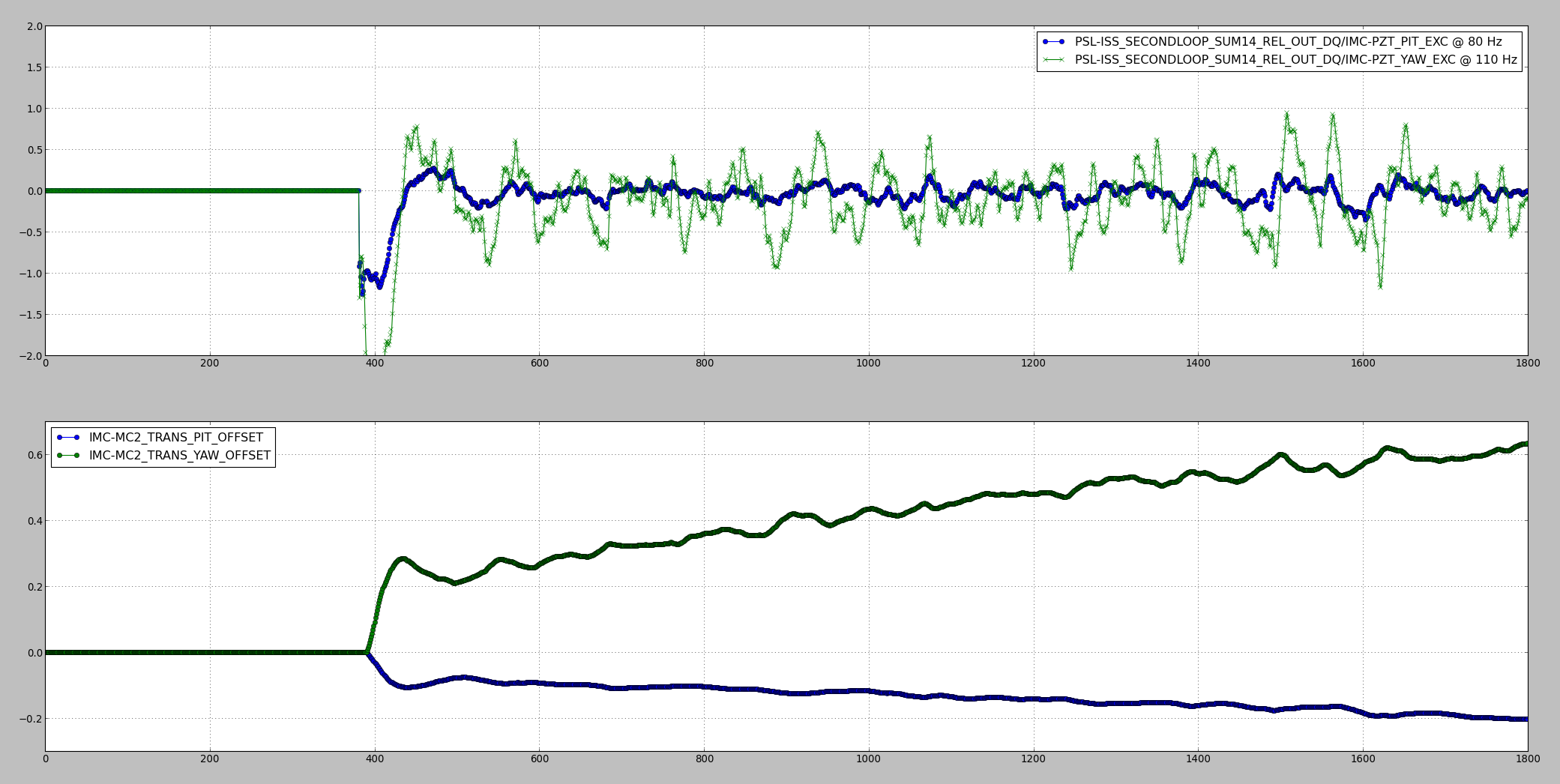
Unfortunately, on a long timescale the offset servo is diverging, as shown in the second loop. The reason seems to be some interaction with the IMC ASC loops: moving the beam on MC2_TRANS adds offsets on the WFS, and then the IMC ASC loops respond slowly. The result is somehow drifting away in DC. So this is not a good soluition.
Increasing the IMC angular loop bandwidth
Duiring my previous attemps I found out that the IMC alignment was responding incredibly slowly to my action. Therefore I estimated the loop bandwidths by measuring their step response time constants:
| Pitch | Yaw | |
|---|---|---|
| DOF1 | 40 s | 80 s |
| DOF2 | 5 min | 4 min |
| DOF3 | 30 min | 30 min |
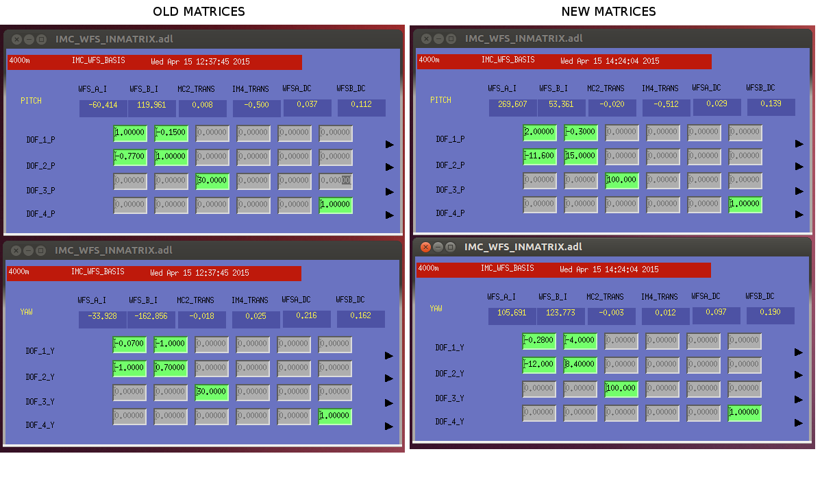
Clearly they were too slow, so I increased all gains to have a bandwidth of about 50 mHz for all of them. To doi this while the loops were closed, I changed the input matrices, as shown in the third attachment. I checked that after this modification all loops have indeed a step response of the order of 20 seconds. There is however a very larg cross coupling of all loops, confirming the result explained in the previous section.
Improving intensity noise with DOF1/2 offsets
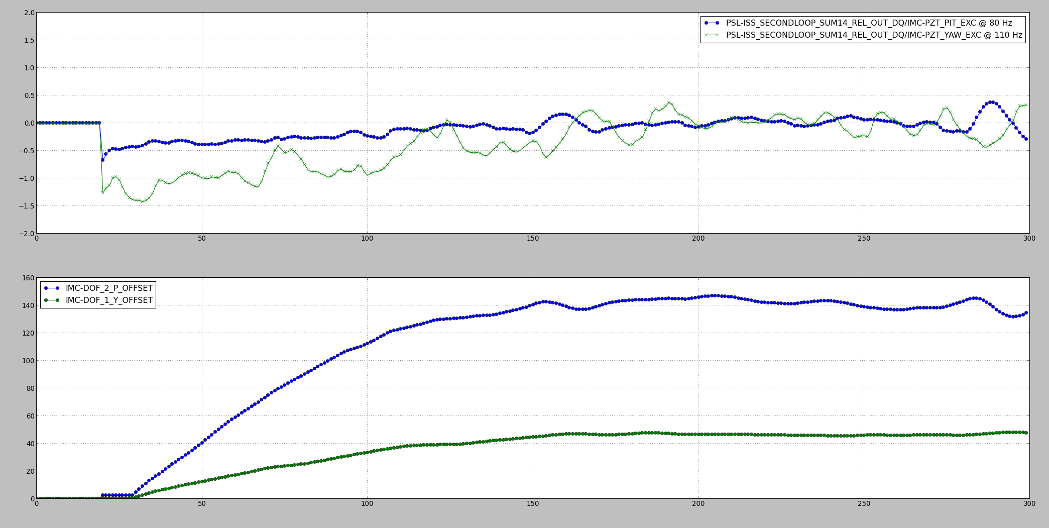
Although this is a less clean solution, I tried to minimze the intensity noise by acting on the DOF_1 and DOF_2 offsets, or in other words of the WFS_A/B offsets. It turned out that the best choice is to act on DOF_1_Y and DOF_2_P, since this is the combination that effectively zero the error signals without affecting significantly the IMC transmitted power. I adapted my script to servo those two offsets to move the error signals to zero. The result is shown in the fourth attachment.
You can use the attached script, provided that you first switch on the two following dither lines:
H1:IMC-PZT_PIT_EXC ampl. 3 frequency 80 Hz
H1:IMC-PZT_YAW_EXC ampl. 3 frequency 110 Hz
The coupling is still fluctuating quite a lot, expecially for the yaw degree of freedom.
I left some offsets in the two degrees of freedom, as found by the script servo: DOF_2_P = 135.9, DOF_1_Y = 47.5

Isn't the bandwidth f_BW = 1/(2pi tau)? Meaning, more like 10mHz with a 20sec response time.