I made another study regarding the low DARM cavity pole issue (alog 17863). This time, I studied effect of losses in the arm cavities and SRC to see how they behave.
A conclusion is that we need a relatively large loss of approximately 7% in SRC in order to explain a DARM cavity pole of 290 Hz.
(The DARM cavity pole model)
I approximated the system to a three-mirror-coupled-cavity so that it has SRM, ITM and ETM in series. I assumed no DARM offset for simplicity. Doing some algebra, one can get a set of cavity equations and therefore the DARM cavity pole as well. In an analytic form, one can write the DARM cavity pole as
f_cavp = C / (4 * pi * L_arm) * abs( log( (re*ri - re*rs) / (1 - ri*rs) ) ).
To derive the above equation, I neglected loss in ITM (so that ri^2+ti^2 = 1) and also the phase rotation of the audio sidebands in SRC as usual. Since the system is compactified to the three-mirror configuration, it does not allow one to add differential arm losses (unless you do something tricky).
(The effect of losses)
I added loss on ETM (which is equivalent to common loss in the arm cavities in reality) and SRM (which should be equivalent to a SRC loss). The attached plot below shows the frequency of the DARM cavity pole as a function of either arm loss or SRC loss.
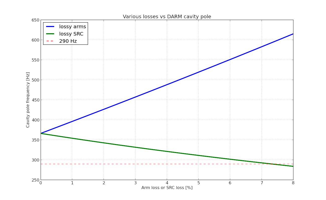
The blue curve is the cavity pole frequency as a function of arm loss with zero SRC loss. The green curve is the one without arm loss but with loss in SRC. As seen in the plot, adding loss in the arm cavities increases the cavity pole frequency. This is intuitively correct as the arm cavity itself is now becoming low-Q and hence wider linewidth. On the other hand adding loss in SRC decreases the cavity pole because adding loss essentially diminishes the signal-recycling effect so that the DARM cavity pole tends to go back to its nominal single arm cavity pole which is at 42 Hz.
In order to get a cavity pole of 290 Hz (which is drawn as a dashed red line in the plot), we need a large loss of about 7% in SRC. Since SRC is formed by a low reflective SRM (T = 37%), one needs a loss comparable to the transmissivity of SRM in order to significantly change the property of the SR cavity.
The python script for making the plot is also attached.
