gabriele.vajente@LIGO.ORG - posted 15:17, Monday 20 April 2015 (17959)
Simulation of SRCL to DARM coupling
I simulated to coupling of SRCL displacement noise into DARM signal, for a full dual recycled interferometer with aLIGO like parameters. The longitudinal locking point is tuned by zeroing the simulated error signals, in the same way it's done in the real world.
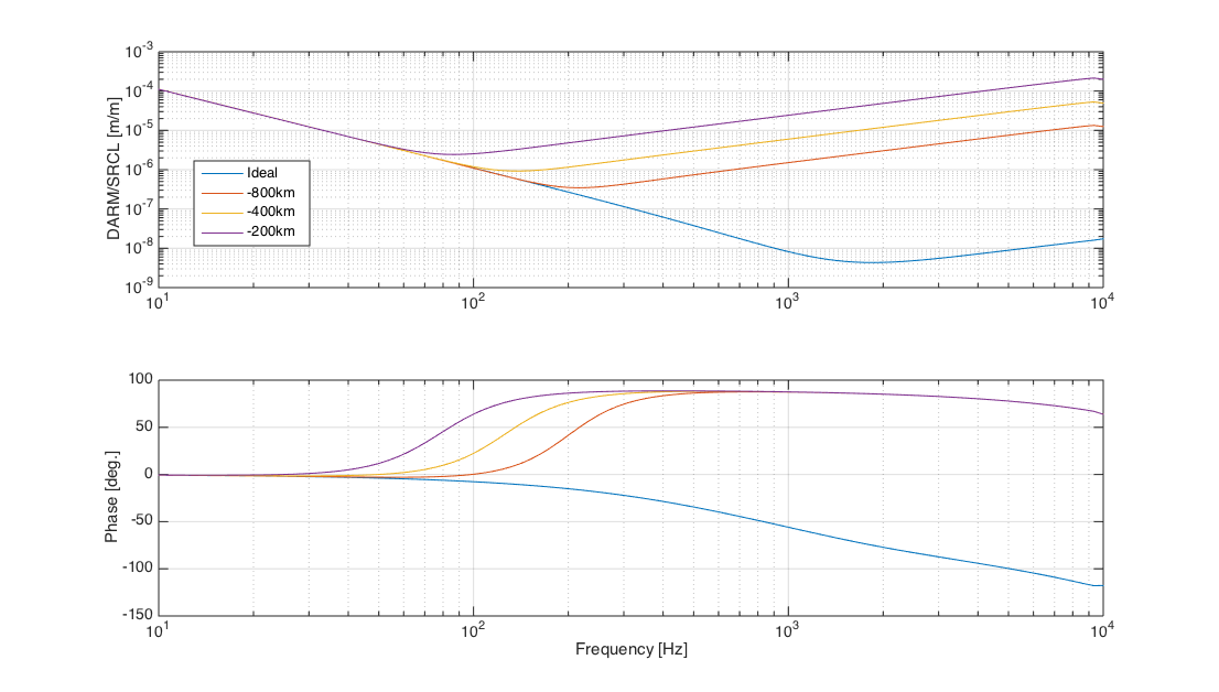
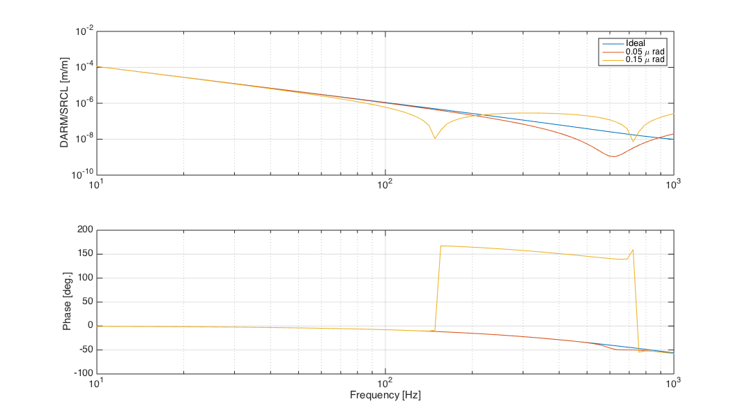
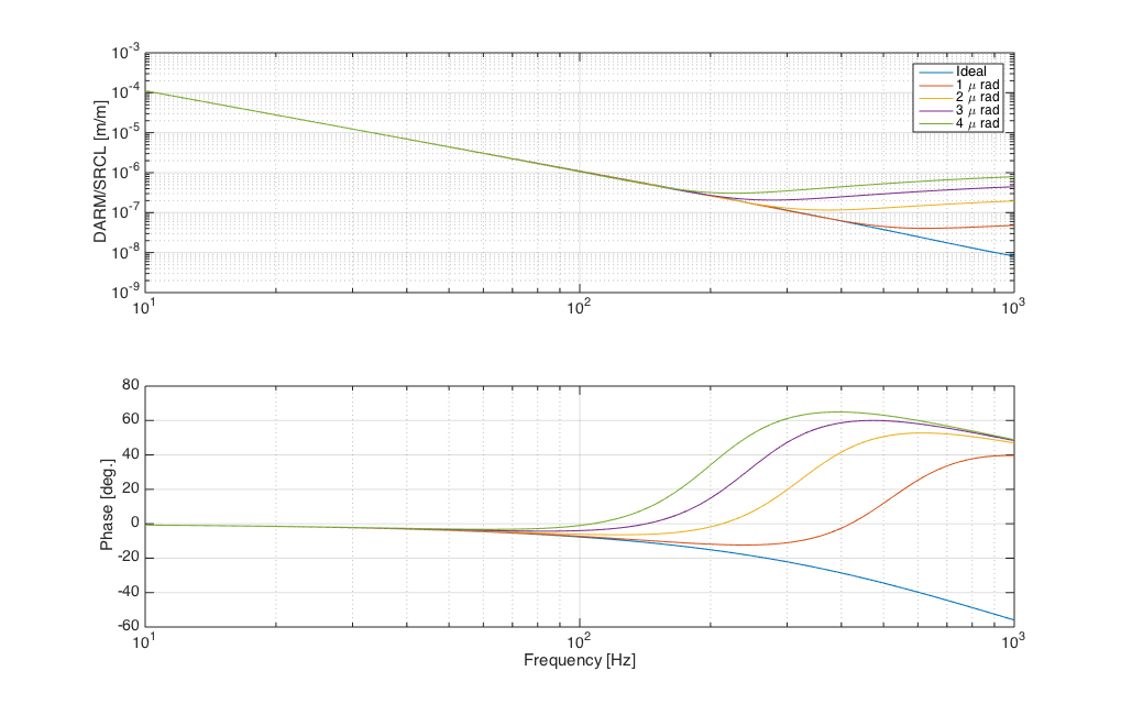
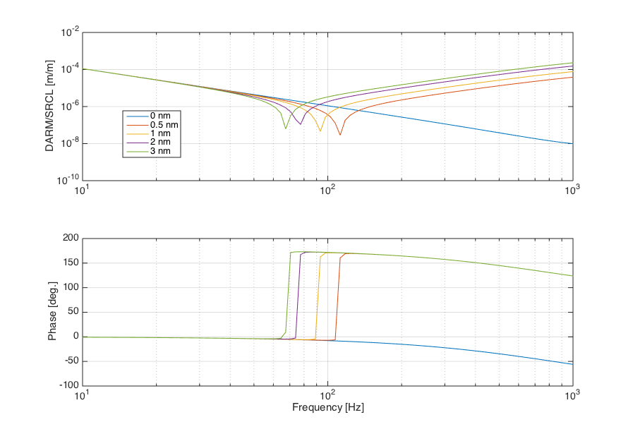
In summary, the coupling of SRCL to DARM, in the ideal case, is a straight 1/f^2 line. However, it's easy to add an additional high frequency component, rising as f^2, by adding some defects:
- figure 1: a common lensing is added. The HF component is present with apparently the same sign as the low frequency one, so that there is no notch in the resulting transfer function.
- figure 2: a common ETM misalignment is added. The HF component has opposite sign and a notch appears. However, to move the ntch down below 100 Hz one should add a very large misalignment, which is unlikely to be there in the real world
- figure 3: a SRM misalignment does not have a significant impact
- figure 4: a longitudinal SRC offset has a very large effect. Indeed this seems the better explanation for the measured coupling of SRCL to DARM both at LLO and LHO. In the LHO case, changing the ITM lens might have the effect of adding an effective SRCL offset
So my guess is that at LLO the change in the TF is due to a SRCL longitudinal offset. The non stationarity of the noise at LHO can be explained both with angular motion of the ETMs and residual SRCL fluctuation.
Images attached to this report