As reported in the previous alog (17990), we noticed that the IM4 trans has shifted by -0.7 counts horizontally after the pzt move (alog 17976) yesterday. I think that we have introduced a horizontal translation in the beam on the PSL mirrors by about 2 mm during the pzt move which resulted in the different IMC output beam alignment. I corrected the alignment of the IMC output beam, by moving IM2 and IM4 this morning.
(Estimation of the shift)
I did an A2L measurement (see Jax's alog 6676 for more details) on MC1 and MC3 to measure the amount of off-centerings. Since we have an active control for the MC2 spot position (DOF3), I did not measure it assuming the in-vac MC2 trans QPD has not moved. The table below summarizes the measurement from today with ones from Dec-2013 for comparison:
| Apr-22-2015 | Dec-13-2013 (alog 8943) | diff (today - past) | |
| MC1 P | +2.2 mm | -1.8 mm | +4.0 mm |
| MC1 Y | +3.1 mm | +1.2 mm | +1.9 mm |
| MC3 P | -2.0 mm | +1.7 mm | - 3.7 mm |
| MC3 Y | -4.6 mm | - 2.2 mm | - 2.4 mm |
Since we know that the vertical position on IM4 trans did not change this time, we ignore them for now. Apparently the horizontal position shifted by 1.9 mm and -2.4 mm on MC1 and MC3 respectively. Note that the MC1 and 3 have a beam radius of 2.12 mm (see T0900386-v7) and therefore the shift is as big as the beam size. If we believe these numbers, the beam must have shifted as depicted in the below cartoon:
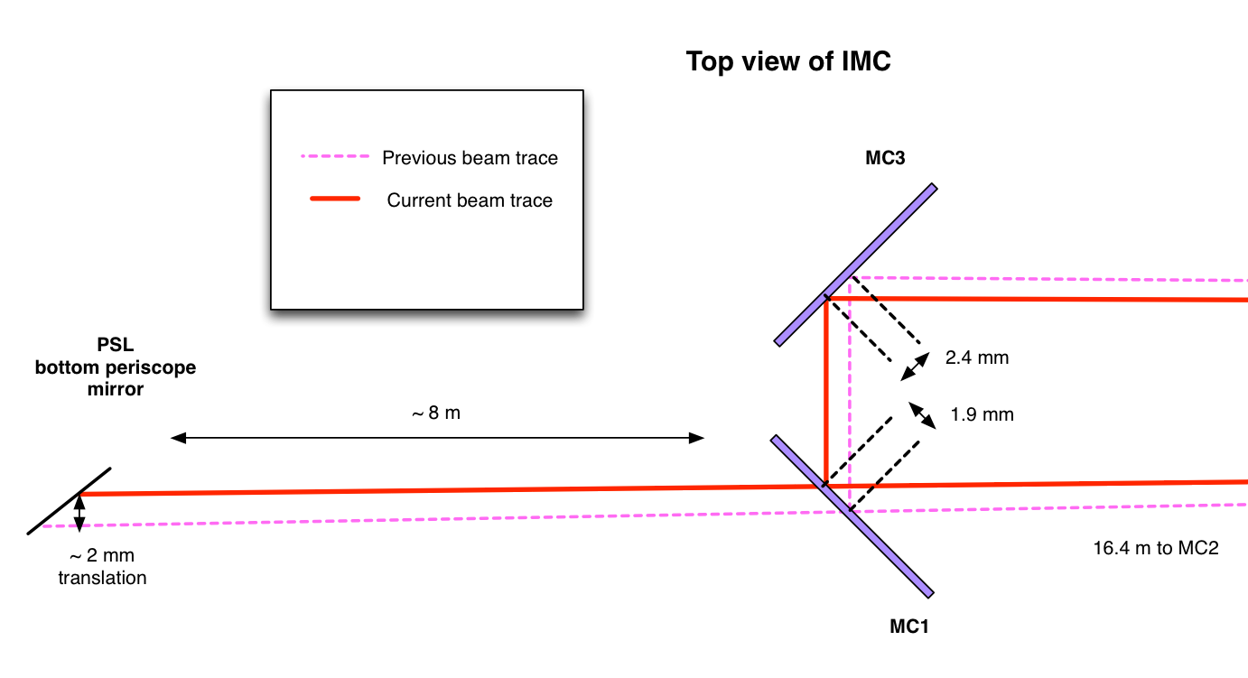
Assuming that the distance from a mirror at the bottom of PSL periscope to MC1 is roughly 8 m, the translation we have introduced is about 2 mm toward the West, which I think does not sound too crazy.
If we want, we can correct this by steering a combination of some mirrors in the PSL so as to compensate the translation.
(Doublecheck with MC suspension biases)
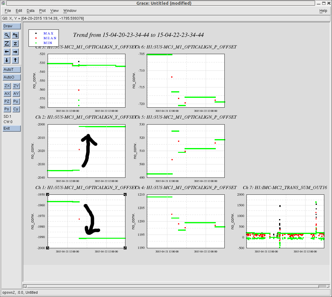
In addition to the spot position measurement, I also checked the suspension bias sliders for double check. According to 2 days trend of the suspension bias values, it seems that the ASC servos introduced 35 urads differential yaw on MC1 and MC3 while MC2 did not move much in yaw after the pzt move. I attach a screen shot of the trend. Though, I have no idea what was happening in the vertical directions which also show some variation. Based on a geometrical arrangement of the IMC alignment (for example, J.opt.13 055504 ), one can write the amount of mis-centering on MC1 and OMC3 due to differental angles as
x_mc1 = -x_mc3 = 2 * sqrt(2) * L * theta_mc1
Substituting theta_mc1 = 35 urad, one can obtain x_mc1 = 1.6 mm for MC1 (and -1.6 mm for MC3). So this is consistent with the spot position measurement and explains large fraction of it.
(Moving IM2 and IM4)
I decided to correct the output beam of IMC by moving some combination of IMs in order to keep the same PRM spot position. Since I did not like moving IM1 as it is far from the input Faraday, I decided to move IM2 to recover the spot position on IM4 trans. Then I corrected the angle of the beam by steering IM4. Here is a table summarizing how much I moved the bias sliders.
| before | after | |
| IM2 YAW bias | 5274 urad | 3314 urad |
| IM4 YAW bias | -5130 urad | -3430 urad |
The direction of the move on IM2 is consistent with the above arguments. Fortunately, the move on IM2 and IM4 were such that they reduced the absolute numbers.