Kiwamu, Keita, Elli
Today locked aux laser to swept frequency offset to carrier laser using PLL. A network analyser provides a swept LO signal (7dBm into ZFM-4+ frequency mixer, or 10dBm if using a splitter.) The RF signal is the beatnote of carrier and aux laser frequencies, which is demodulated against the LO using a ZFM-4+ mixer and 1.9MHz low-pass filter. This error signal is sent to an LG1005 servo controller, P-I corner 10kHz, gain 4.1, LFGL 50dB. We amplified the RF sigal (1611 pd on IOT2R) using 17dB ZFL-1000+ RF amplifier, as the error signal of the PLL was very weak; this made locking the PLL easier. The PSL pwer was 2.3W, the aux laser power set to 500mW.
We noticed changing IM4 alignment during initial alignment changes alignment of beams onto the 1611 photodiodes enough that a quick realignment may be necessary. This is a little painful as this alignment is done on IOT2R, where the aux laser is. The aux laser frequency takes some time to settle after opening the table. Again today we used the 1611 pd on ISCT1. I unplugged the power to the bbpd-refl photodiode (the 3f refl pd) in order to power the 1611, and then changed this back again after I was done.
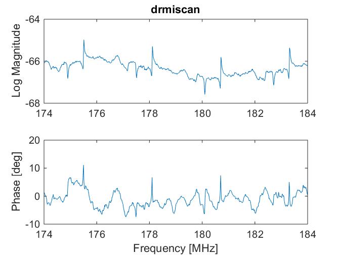
To take the measurement we locked DRMI 1f with ASC. To engage PRC1, we adjusted the centering offset on Refl-DC WFS. We looked at the signal reflected from DRMI using a 1611pd on ISCT1 on the reflair path, and measured the transfer function of this reflected light intensity over the LO frequency. Could see transmission dips every ~2.6MHz, which correspond to the auxiliary laser resonance in PRC. Also some other peak which may be higher order mode. Currently producing a model to make sense of this, and to decide what frequencies will be useful to measure at.